3Installing the option devices
Installing the J1 axis operating range change (RV-4FR/7FR/13FR series)
3-55
3.2 Installing the J1 axis operating range change (RV-4FR/7FR/13FR series)
The configuration, changeable angle and installation outline of J1 axis operating range change are shown below.
3.2.1 RV-4FR/7FR series
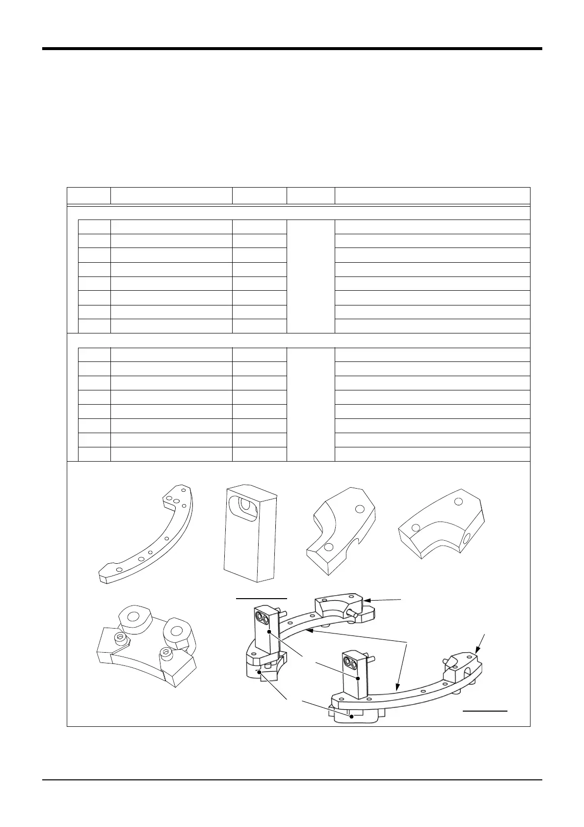
(1) Configuration
The configuration parts of this option are shown in Table 3-7. Please confirm.
The option for RV-4FR series is 1F-DH-03, and RV-7FR series is 1F-DH-04.
Table 3-7 : Configuration devices
No. Part name Qty. Mass (kg) Remarks
RV-4FR series
<1> Stopper plate 2
1.1
One piece each for + side/- side
<2> Fixing block A 2 One piece each for + side/- side
<3> Fixing block B 1 + side
<4> Fixing block C 1 - side
<5> Variable stopper block 2 One piece each for + side/- side
<6> Screw (M10x20) 2 Use for mechanical stopper screw A and B
<7> Screw (M6x25) 2 For fixing
<8> Screw (M6x20) 16 For fixing
RV-7FR series
<1> Stopper plate 2
1.1
One piece each for + side/- side
<2> Fixing block A 2 One piece each for + side/- side
<3> Fixing block B 1 + side
<4> Fixing block C 1 - side
<5> Variable stopper block 2 One piece each for + side/- side
<6> Screw (M12x25) 2 Use for mechanical stopper screw A and B
<7> Screw (M8x25) 14 For fixing
<8> Screw (M8x20) 4 For fixing
<1>
<5>
<4>
<3>
<2>
+ (plus) side
- (minus) side
<1> Stopper plate <2> Fixing block A <3> Fixing block B <4> Fixing block C
<5> Variable stopper block
 Loading...


