CHASSIS ELECTRICAL
-
Ignition Switch
54-7
REMOVAL SERVICE POINTS
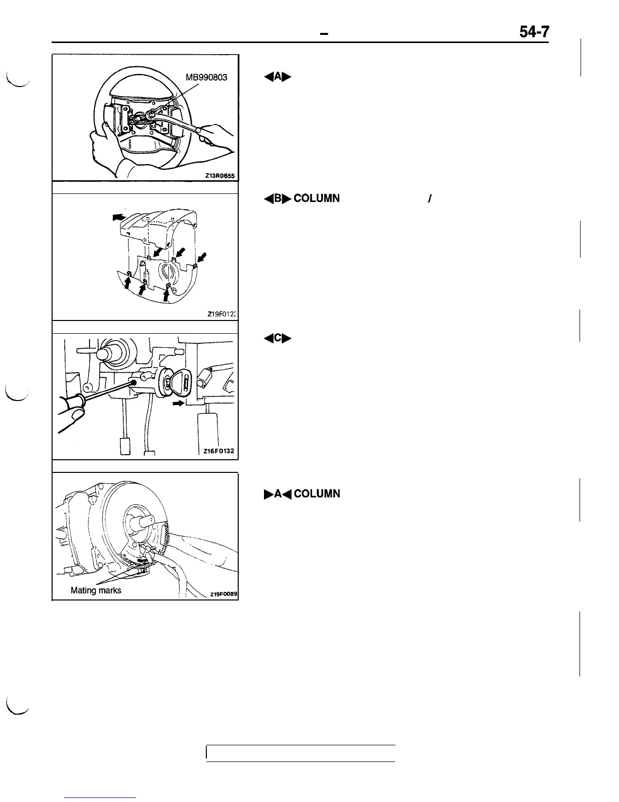
+A,
STEERING WHEEL REMOVAL
Remove the steering wheel by using the special tool.
Caution
Do not hammer on the steering wheel to remove it;
doing so may damage the collapsible mechanism.
Front of vehicles
219FO12:
+B,COLUMN
COVER LOWER
/
COLUMN COVER
UPPER REMOVAL
After the screws have been removed, remove the covers,
while making sure not to break the grippers.
+C,
STEERING LOCK CYLINDER REMOVAL
(1) Insert the ignition key into the steering lock cylinder
and place the key in the ACC position.
(2)
Press the lock pin down with a Phillips head screwdriv-
er (small-size one) to remove the steering lock cylinder.
INSTALLATION SERVICE POINT
.A+COLUMN
SWITCH AND CLOCK SPRING
ASSEMBLY INSTALLATION
Line up the “NEUTRAL” mark of the clock spring with
the mating mark to center the clock spring.
Caution
If the clock spring is not centered, problems such
as intermediate failure of the steering wheel to turn,
broken ribbon cable in the clock spring, or the like
could occur. As a result, they might hinder proper
operation of the SRS, resulting in serious injury.
i
I
1
TSB Revision
I

 Loading...