6. BASE UNIT AND EXTENSION CABLE
6 - 7
MELSEC-
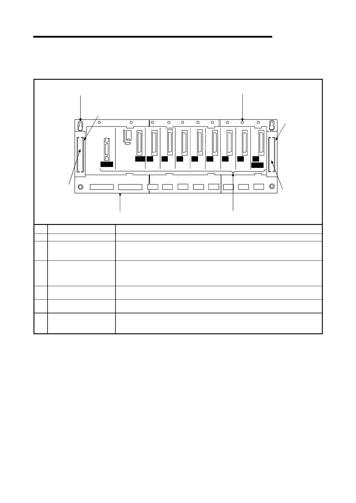
6.2 Parts Identification and Setting
(1) Main base unit (A1S32B, A1S33B, A1S35B, A1S38B)
(5)
(1)
(4)
(1)
(2)
(3)
(6)
(2)
IOUT IOUT
POWER
CPU I/O
0
I/O
1
I/O
2
I/O
3
I/O
4
I/O
5
I/O
6
I/O
7
A1S38B
No. Name Application
(1) Connector for extension cable Connector for sending and receiving signals to and from the extension base unit.
(2) Base cover
Cover to protect the connector for the extension cable.
When connecting an extension cable, remove the appropriate base cover located below the
word "OUT" with nippers or a similar tool.
(3) Module connectors
Connectors where the power supply module, CPU module, I/O module, special function
modules are loaded.
Fit the connector cover or blank cover (A1SG60) to vacant connectors, in order to protect the
module from dust.
(4) Module fixing screw
Screw to fix a module to the base unit.
Screw size : M4
×
12 screw
(5)
Guide hole for base
installation
Slot for mounting this base unit to the panel of control box, etc. (For M5 screw)
(6) DIN rail hook
Hook to install on a DIN rail.
A1S32B, A1S33B
.......
1
A1S35B, A1S38B
.......
2

 Loading...