INSTALLATION AND WIRING
19
2.2.3 Wiring of the control circuit
(
1
)
Wiring instructions
1) Terminals SD are common terminals for I/O signals. These common terminals must
not be earthed to the ground.
2) Use shielded or twisted cables for connection to the control circuit terminals and run
them away from the main and power circuits (including the 200V relay sequence
circuit).
3) The frequency input signals to the control circuit are micro currents. When contacts
are required, use two or more parallel micro signal contacts or a twin contact to
prevent a contact fault.
4) It is recommended to use the cables of 0.3mm
2
to 0.75mm
2
gauge for connection to
the control circuit terminals.
5) When bar terminals and solid wires are used for wiring, their diameters should be
0.9mm maximum If they are larger, the screw threads may be damaged during
tightening.
(
2
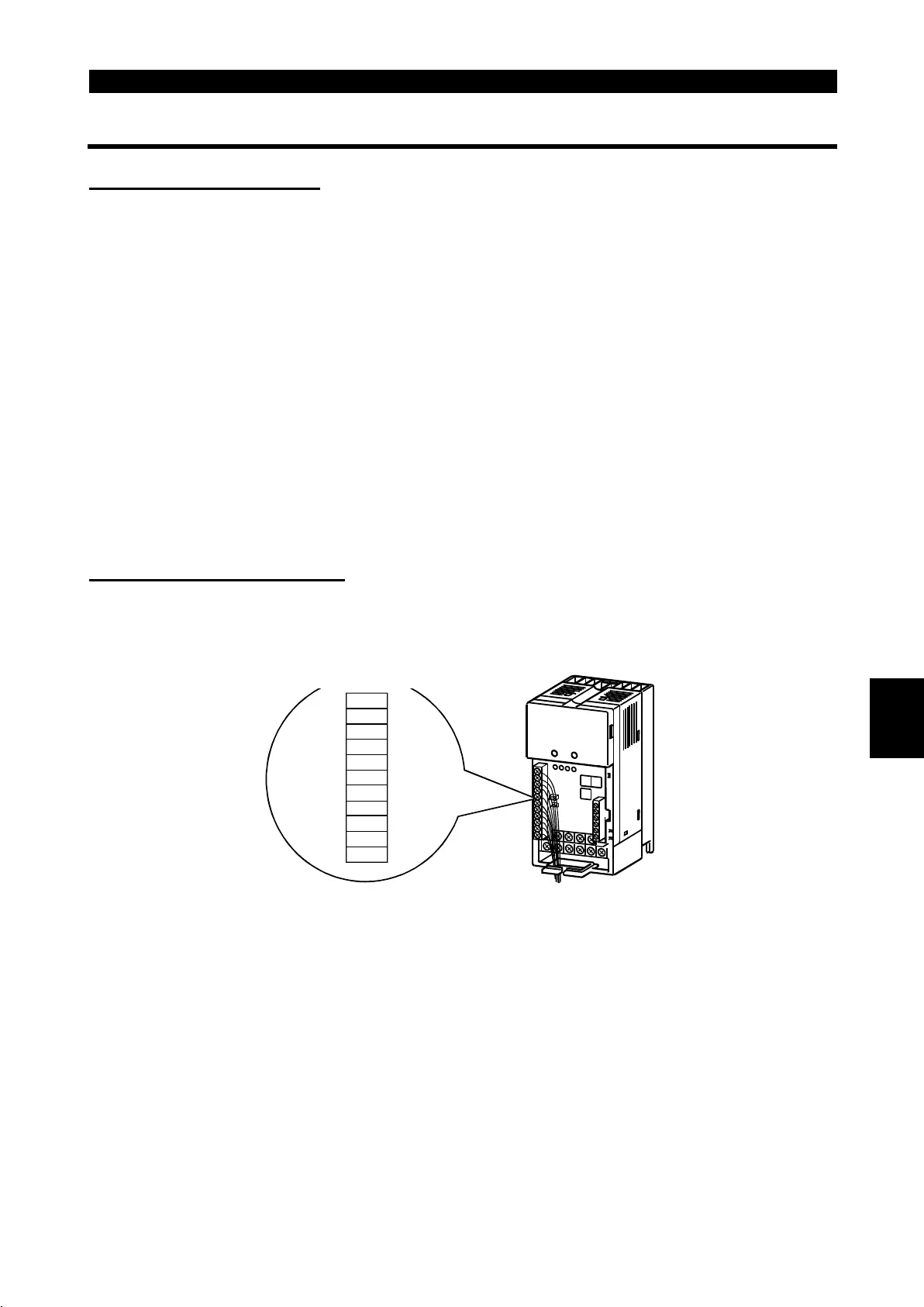
)
Terminal block layout
In the control circuit of the inverter, the terminals are arranged as shown below:
Terminal screw size: M2.5
Terminal layout of
control circuit
P24
P24
SD
SD
MRS
RES
NC
NC
A
B
C
*
*
*: Keep NC unconnected.
2

 Loading...


