3.3 Communication Specifications
54
3.3 Communication Specifications
3.3.1 I/O signal list
The following device No.s are those for station 1.
For stations 2 and later, the device No.s are different. (For the device No.
correspondence list, refer to the master unit manual.)
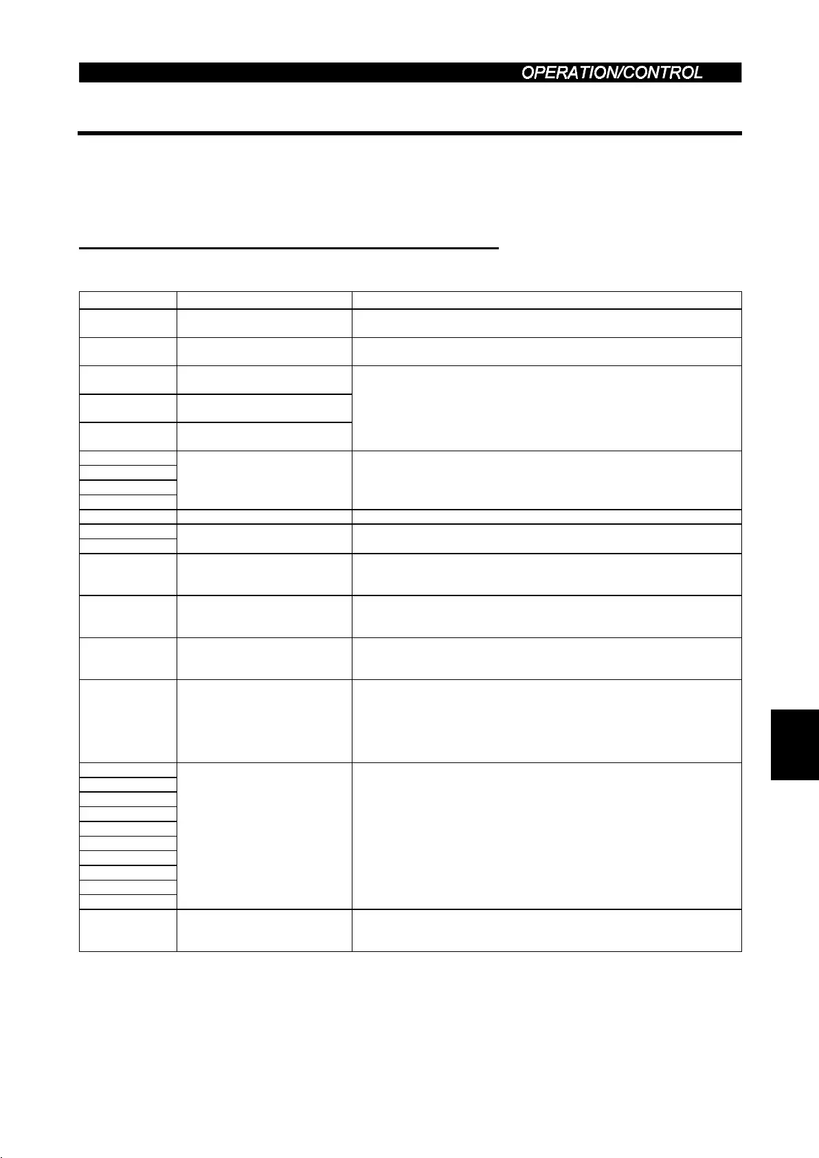
(1) Output signals (master module
→
→→
→
inverter)
The output signals from the master unit are indicated. (Input signals to inverter)
Device No. Signal Description
RY0 Forward rotation command
OFF : Stop command
ON : Forward rotation start (Note 1)
RY1 Reserve rotation command
OFF : Stop command
ON : Reserve rotation start (Note 1)
RY2
RH terminal function
(high speed)
RY3
RM terminal function
(middle speed)
RY4
RL terminal function
(low speed)
Functions assigned to RH/RM/RL are selected.
In the factory setting, multi-speed selection can be made by the
combination of RH, RM and RL. (Note 2)
RY5
RY6
RY7
RY8
Unused (Note 5) Reserved for the system.
RY9 Output halt (MRS) When the MRS signal switches on, the inverter output stops. (Note 2)
RYA
RYB
Reserved (Note 5) Reserved for the system.
RYC Monitor command
When the monitor command (RYC) is switched on, the monitored value is
set to remote register RWr
0
and monitoring (RXC) switches on. While the
monitor command (RYC) is on, the monitored value is always updated.
RYD
(Note 4)
Frequency setting command
(RAM)
When the frequency setting command (RYD) is switched on, the set
frequency (RW
W1
) is written to the inverter. (Note 3) On completion of
write, frequency setting completion (RXD) switches on.
RYE
(Note 4)
Frequency setting command
(E
2
PROM)
When the frequency setting command (RYE) is switched on, the set
frequency (RW
W1
) is written to the inverter. On completion of write,
frequency setting completion (RXE) switches on.
RYF
(Note 4)
Instruction code
execution request
When the instruction code execution request (RYF) is switched on,
processing corresponding to the instruction code set to RW
W2
is
executed. After completion of instruction code execution, instruction code
execution completion (RXF) switches on. When an instruction code
execution error occurs, a value other than 0 is set to the reply code
(RWr
2
).
RY10
RY11
RY12
RY13
RY14
RY15
RY16
RY17
RY18
RY19
Reserved (Note 5) Reserved for the system.
RY1A Error reset request flag
If the error reset request flag (RY1A) is switched on only when an inverter
fault occurs, the inverter is reset and the error status flag (RX1A)
switches off.
Note: 1. Simultaneously turning on RY0 and RY1 gives a stop command.
2. Using Pr. 180 to Pr. 183 (input terminal function selection), you can set the input signals of device No.s RY2
to RY4. For details, refer to page 130.
3. While the set frequency designation (RYD) signal is ON, the value of the set frequency (RW
W1
) is always
reflected.
4. If these signals turn on at the same time, only one of them is executed.
5. The reserved input signal should be off. (Enter 0)
3

 Loading...


