55
(2) Input signals (inverter →
→→
→ master module)
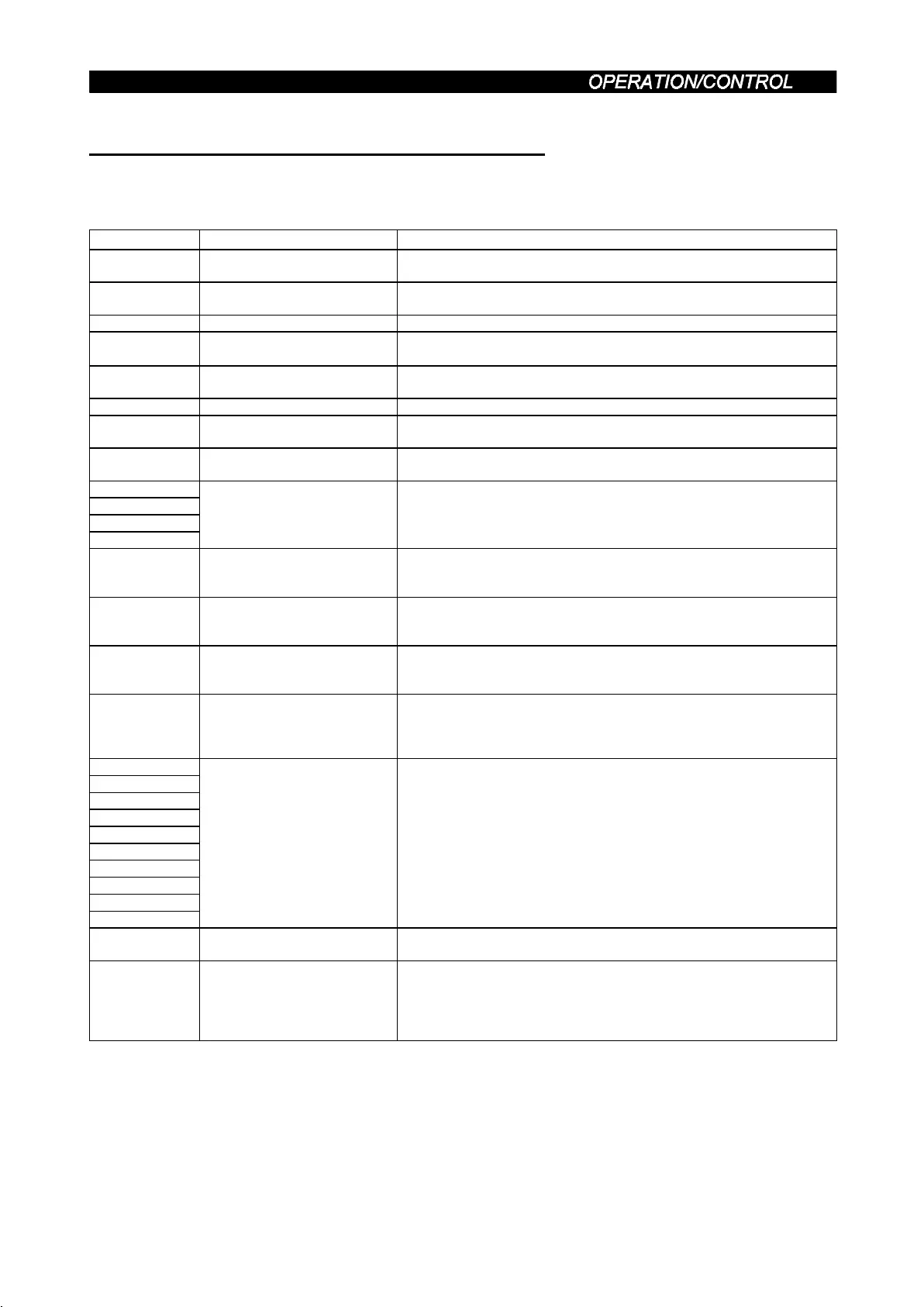
The input signals from the inverter to the master unit are indicated.
(Output signals from inverter)
Device No. Signal Description
RX0 Forward running
OFF : Other than forward running (during stop or reverse rotation)
ON : Forward running
RX1 Reverse running
OFF : Other than reverse running (during stop or forward rotation)
ON : Reverse running
RX2 Running (RUN) On while the inverter is running. (Note 1)
RX3 Up to frequency (SU)
Switched on when the output frequency reaches the set frequency
±
Pr. 41.
RX4 Overload (OL)
Switched on when stall prevention operation is performed, switched
off when stall prevention is canceled.
RX5 Unused Reserved for the system.
RX6 Frequency detection (FU)
Switched on when the output frequency reaches set frequency.
(Note 1)
RX7 Normal (A, B, C)
Switched on when the inverter's protective function is activated to
stop the output. (Note 1)
RX8
RX9
RXA
RXB
Unused Reserved for the system.
RXC Monitoring
Switched on when the monitored value is set to RWr
0
by the monitor
command (RYC) switching on. Switched off when the monitor
command (RYC) is switched off.
RXD
Frequency setting command
(RAM)
Switched on when the set frequency is written to the inverter by the
frequency setting command (RYD) switching on. Switched off when
the frequency setting command (RYD) is switched off.
RXE
Frequency setting command
(E
2
PROM)
Switched on when the set frequency is written to the inverter by the
frequency setting command (RYE) switching on. Switched off when
the frequency setting command (RYE) is switched off.
RXF
Instruction code execution
completion
Switched on on-completion of the processing corresponding to the
instruction code (RW
W2
) which is executed when the instruction code
execution request (RYF) switches on. Switched off when the
instruction code execution completion (RXF) is switched off.
RX10
RX11
RX12
RX13
RX14
RX15
RX16
RX17
RX18
RX19
Reserved Reserved for the system.
RX1A Error status flag
Switched on when an inverter error occurs (protective function is
activated).
RX1B
Remote station ready
(Note 2)
Switched on when the inverter goes into the ready status on
completion of initial setting after power-on or hardware reset.
(Used as an interlock for read/write from/to the master station.)
Switched off when an inverter error occurs (protectiove function is
activated).
Note: 1. Using Pr. 190 to Pr. 192 (output terminal function selection), you can set the output signals of device No.s
RX2, RX6, RX7.
For details, refer to page 132.
2. Since operation differs with the condition setting switch (SW4) position of the master unit, use SW4 in the
OFF position. If you use SW4 in the ON position, the remote station ready signal remains ON if a
communication error occurs.

 Loading...


