52
3.2.2 Function overview
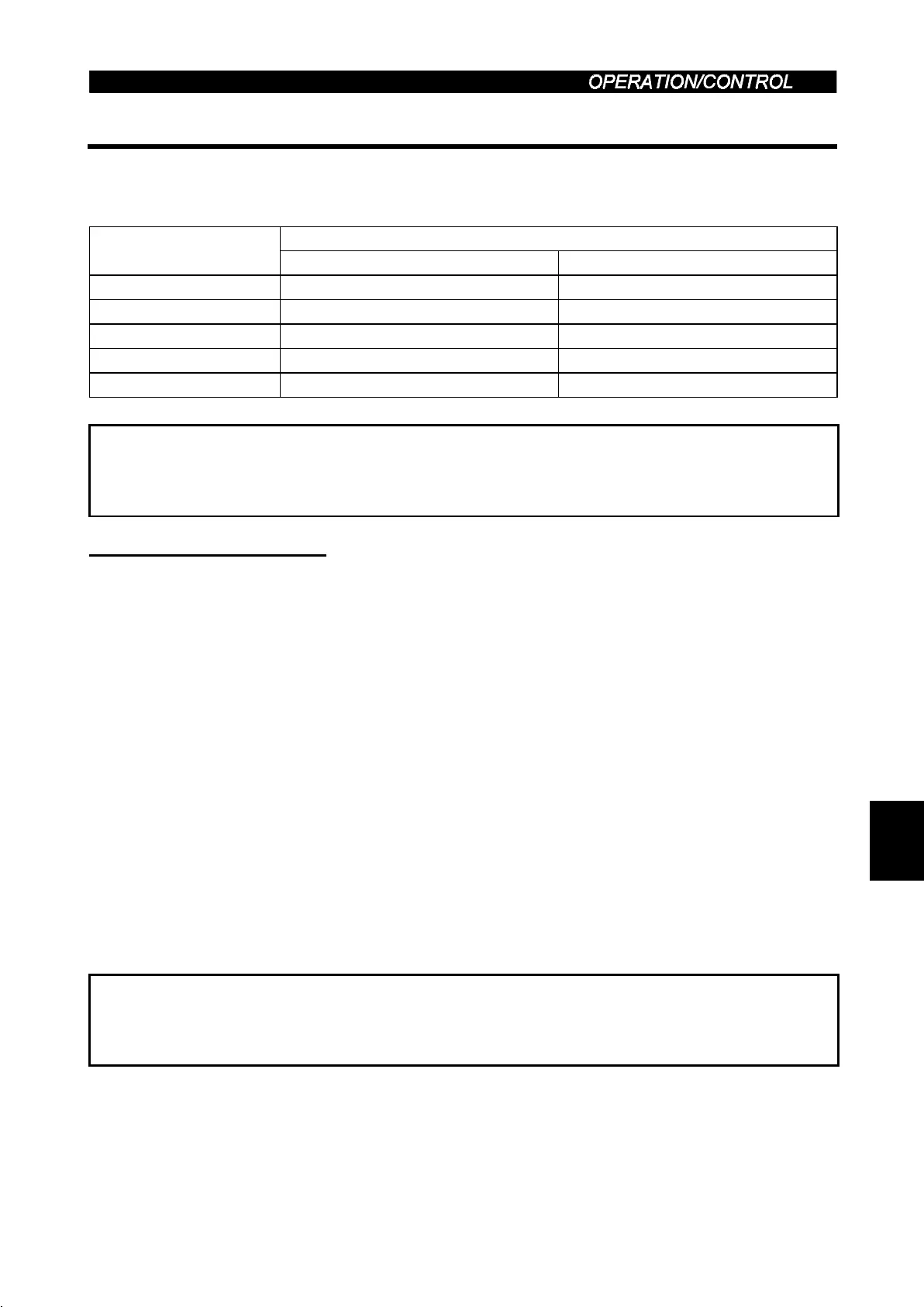
The following table lists the functions that can be performed from the PC in the CC-Link
system:
Operation Mode
Item
CC-Link operation PU operation
Monitoring function Allowed Allowed
Operation command Allowed Disallowed
Parameter write Allowed (Note 1) Disallowed
Parameter read Allowed Allowed
Inverter reset Allowed (Note 2) Disallowed
Note 1. Parameters cannot be written during inverter operation.
2. When a CC-Link fault occurs, the inverter cannot be reset from the PLC.
(For inverter reset, refer to page 148.)
(1) Monitoring function
(Refer to page 61.)
The following items can be monitored by the PLC:
1) Output frequency...............Binary in 0.01Hz increments
2) Output current ...................Binary in 0.01A increments
3) Output voltage...................Binary in 0.1V increments
4) Alarm definition
5) Special monitoring.............Monitored data selected by instruction code F3H
6) Inverter status
· Forward running
· Reverse running
· Running (RUN)*
· Up to frequency (SU)
· Overload (OL)
· Frequency detection (FU)*
· Alarm*
The output signals marked * can be changed using Pr. 190 to Pr. 192 (output
terminal (remote input) function selection).
Note: Items 1) to 4) are read from the buffer memory by setting the corresponding
code numbers when needed.
Item 6) can be read from the buffer memory any time.
3

 Loading...


