3.2 Function Overview
51
3.2 Function Overview
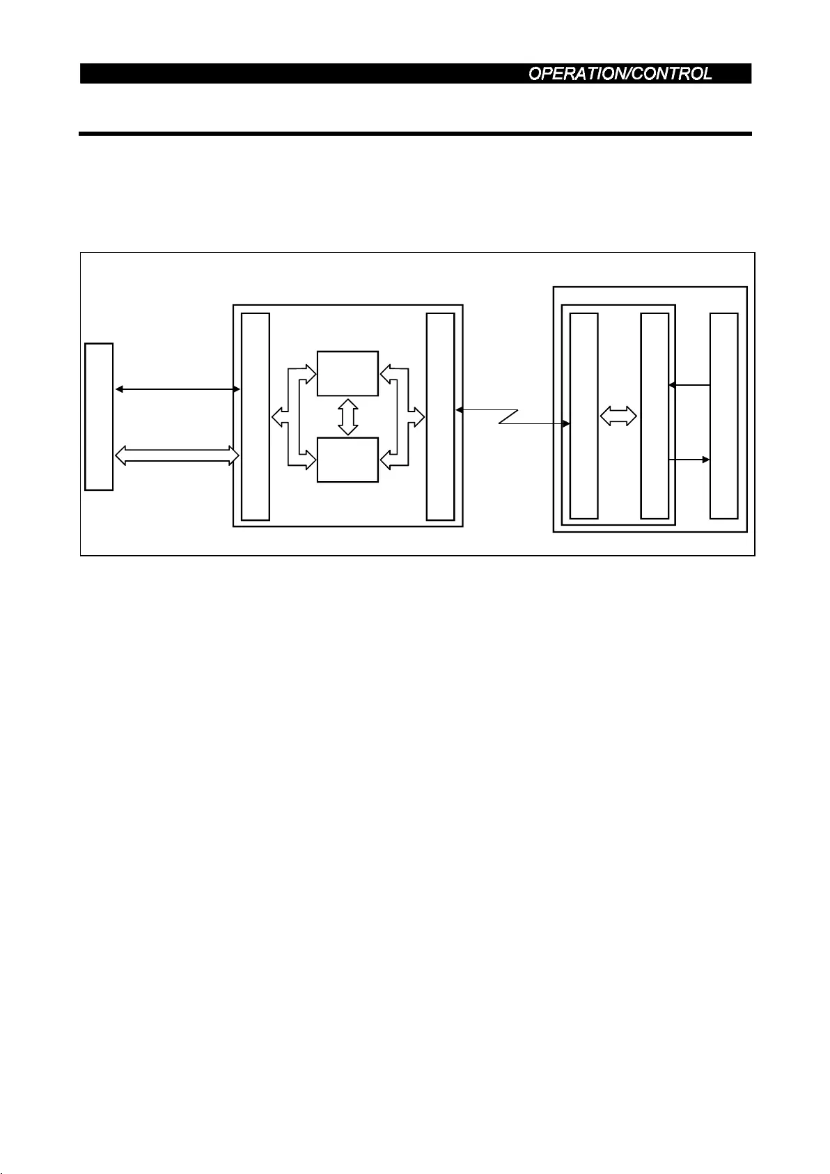
3.2.1 Function Block Diagram
Using function blocks, this section explains I/O data transfer to/from an inverter using
CC-Link.
Link refresh is continuously executed between the master station and inverter in the
CC-Link system at intervals of 1.1ms to 141ms (512 points).
CPU
PLC CPU
1) AJ61BT11
I/O signals
Interface with PLC
Buffer
memory
CC-Link interface
3) CC-Link
dedicated
cable
Inverter
CC-Link interface
I/O interface
Input
Out-
put
Inverter CPU
2) Buffer memory
access
PLC system master/local CC-Link module
1) I/O signals assigned to the CC-Link system master/local unit.
These signals are used for communication between the PLC CPU and CC-Link
system master/local unit.
For further details of the signals, refer to page 54.
2) You can read input data from the inverter, write output data to the inverter, and read
CC-Link faulty station, for example. Use the FROM/TO instruction in the sequence
program to access the buffer memory. (When the automatic refresh function is used,
the FROM/TO instruction is not needed.) For details of the buffer memory, refer to
the CC-Link system master/local module manual.
3) Direct a PLC link start from the sequence program. After CC-Link has started, link
refresh is always made asynchronously (synchronously) with the execution of the
sequence program.
For details, refer to the CC-Link system master/local module manual.

 Loading...


