INSTALLATION AND WIRING
21
Note:1. Make sure that the front cover has been installed securely.
2. The front cover has a capacity plate and the inverter a rating plate on it.
Since these plates have the same serial numbers, always reinstall the
removed cover to the inverter from where it was removed.
3. Always install the sink-source logic changing connector in either of the
positions. If two connectors are installed in these positions at the same time,
the inverter may be damaged.
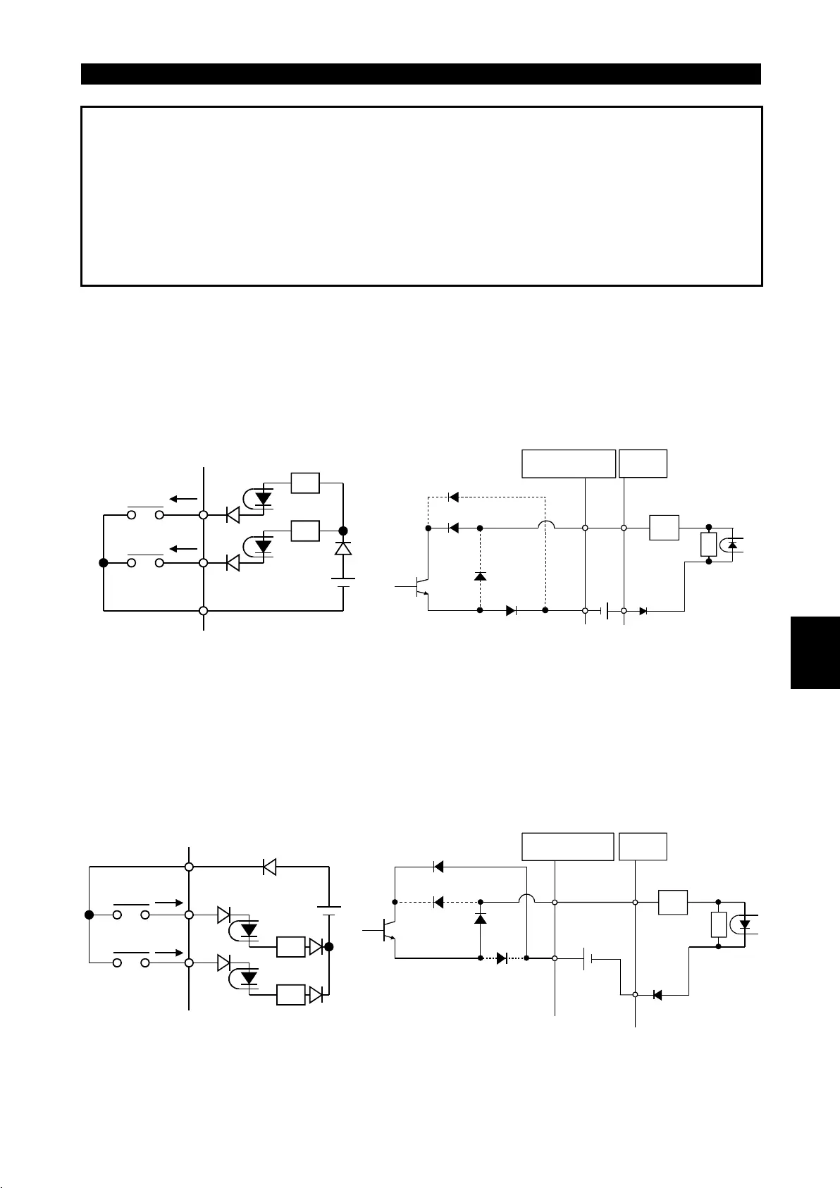
2) Sink logic type
!
In this logic, a signal switches on when a current flows out of the corresponding
signal input terminal.
Terminal SD is common to the contact input signals.
Terminal SE is common to the open collector output signals.
R
R
Current
MRS
RES
SD
AX40
SE
RUN
24VDC
R
1
9
R
• Current flow related
to RUN signal
Inverter
3) Source logic type
!
In this logic, a signal switches on when a current flows into the corresponding signal
input terminal.
Terminal P24 is common to the contact input signals.
Terminal SE is common to the open collector output signals.
R
R
Current
RES
MRS
P24
AX80
24VDC
RUN
SE
1
9
R
R
• Current flow related
to RUN signal
Inverter
2

 Loading...


