INSTALLATION AND WIRING
24
(5)
Recommendation of bar terminals
For wiring of the CC-Link communication signals, two CC-Link dedicated cables must
be twisted together and connected to one terminal block.
When using bar terminals, the following terminals and tool are recommended.
1) Recommended bar terminal, crimping tool
!
Company: Phoenix Contact Co., Ltd.
!
Bar terminal type: AI-TWIN2
×
0.5-8WH
!
Crimping tool type: CRIMPFOX UD6, ZA3
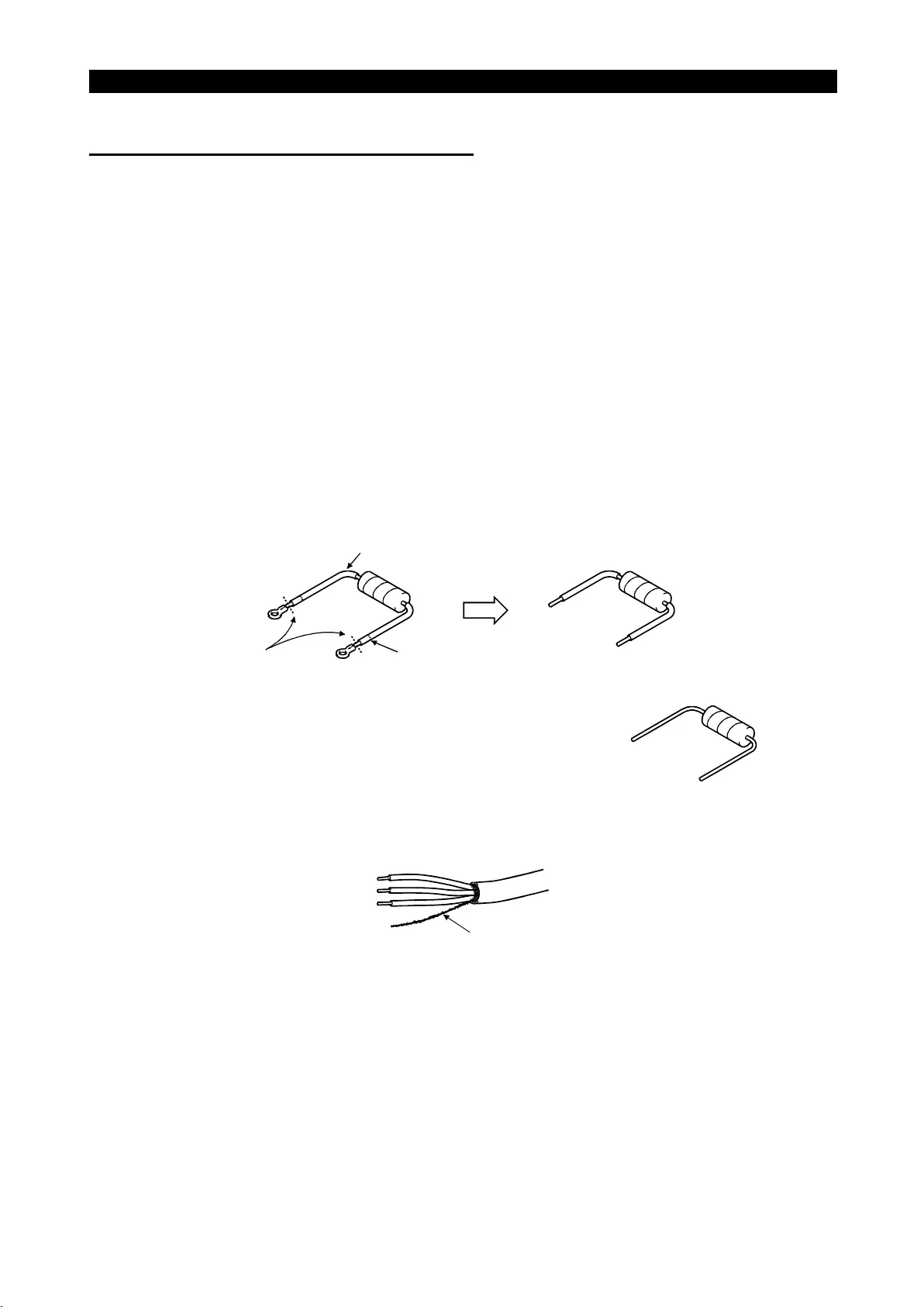
2) Connection of terminal resistor
Connect a terminal resistor between terminals DA-DB of the inverter located at the
end.
Work the resistor attached to the master unit of the PLC for use as the terminal
resistor.
Cut.
Cut the tube.
Tube
Note: When there is no resistor attached to the
master unit, use a commercially available
110
Ω
, 1/2W resistor.
3) Connection of shield wire of the CC-Link dedicated cable
Twist the shield wire of the CC-Link dedicated cable and connect it to terminal SLD.
Shield wire
Note: The two SLD terminals are connected in the inverter.

 Loading...


