133
FX3G/FX3U/FX3GC/FX3UC Series
Programming Manual - Basic & Applied Instruction Edition
4 Devices in Detail
4.10 Extension Register [R] and Extension File Register [ER]
1
Introduction
2
Overview
3
Instruction
List
4
Devices
in Detail
5
Specified the
Device &
Constant
6
Before
Programming
7
Basic
Instruction
8
FNC00-FNC09
Program Flow
9
FNC10-FNC19
Move & Compare
10
FNC20-FNC29
Arith. & Logic
Operation
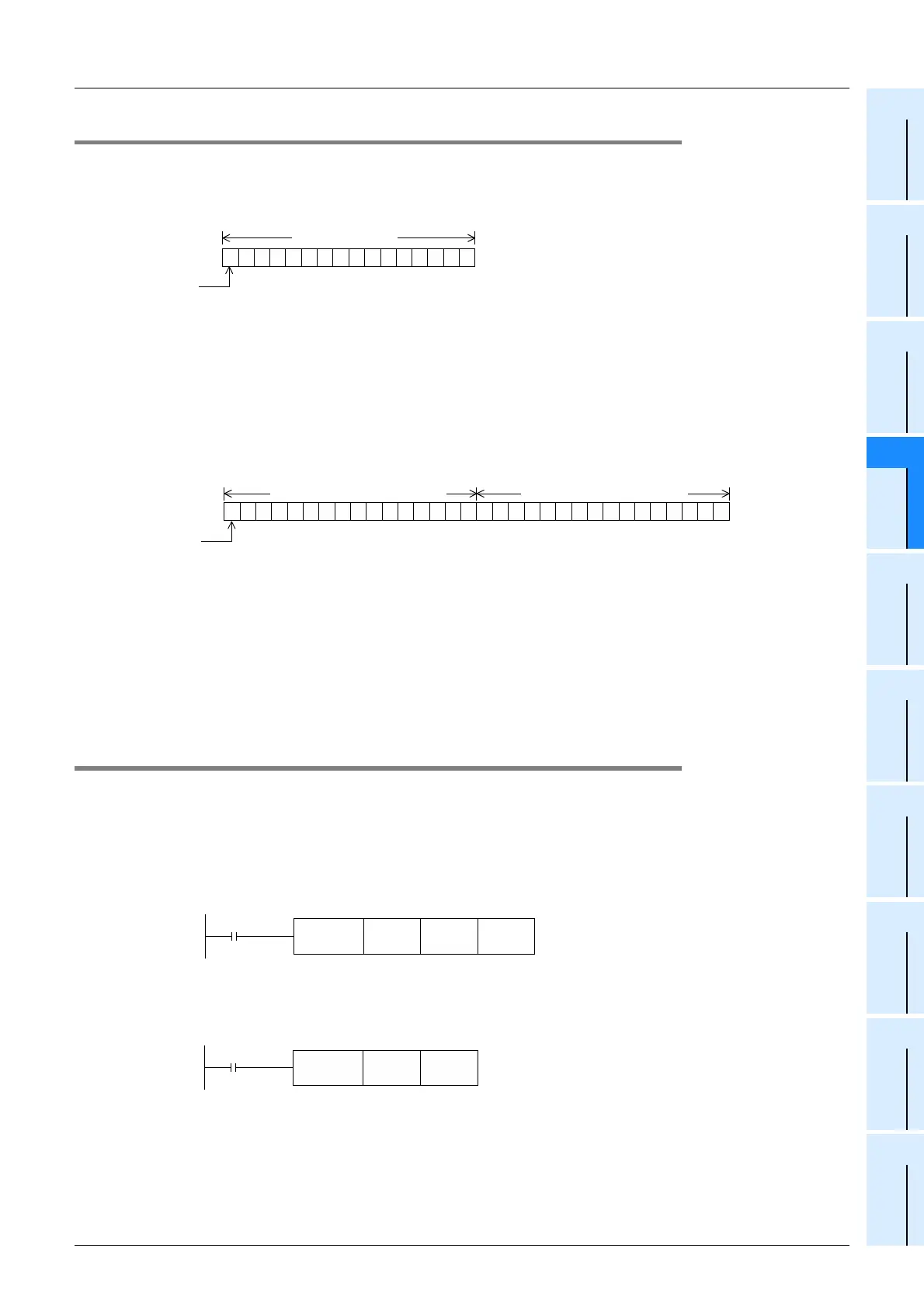
4.10.3 Structures of extension registers and extension file registers
One extension register consists of 16 bits. Extension registers can be used in 16-bit and 32-bit applied instructions in
the same way as data registers.
1) 16-bit type
One extension register (consisting of 16 bits) can handle a numeric ranging from −32768 to +32767.
A numeric value is usually read from and written to an extension register by applied instructions.
However, a numeric value can also be directly read from and written to an extension register from a display unit,
display module, or programming tool.
2) 32-bit type
Two serial extension registers (consisting of 32 bits) can express a 32-bit numeric value ranging from
−2,147,483,648 to +2,147,483,647. (A larger number register handles high-order 16 bits, and a smaller number
register handles low-order 16 bits.)
• In the case of 32 bit type, when an extension register on the low-order side (example: R0) is specified, the
subsequent serial number on the high-order side (example: R1) is automatically occupied.
Either an odd or even device number can be specified for the low-order side, but it is recommended to specify an
even device number for the convenience of the monitoring function for display units, display modules, and
programming tools.
4.10.4 Initialization of extension registers and extension file registers
The contents of extension registers are backed up by the battery even when the power is turned OFF or when the PLC
mode switches from STOP to RUN in FX3U/FX3UC PLCs and in FX3G/FX3GC PLCs if extension registers are changed
to the latched (battery backed) type and the optional battery is installed.
When initializing the contents of extension registers, clear them using a sequence program or GX Developer.
1. When clearing the data using a program
• When initializing some extension registers (R)
Example: When initializing (clearing) R0 to R199
• When initializing extension registers and extension file registers in sector units
Sectors are not provided for extension registers and extension file registers in FX3G/FX3GC PLCs.
Example: When initializing R0 to R4095 and ER0 to ER4095 (initializing two sectors starting from R0 and ER0)
2. When clearing the data using GX Developer
Select [Online] → [Clear PLC memory...] in GX Developer, and clear [Data device].
This operation initializes the contents of timers, counters, data registers, file registers and extension registers.
1010101010101010
1
2
4
8
16
32
64
128
256
512
1024
2048
4096
8192
16384
b15
Sign
0: Positive
number
1: Negative
number
b0
High
order
Low
order
R0, ER0 (16 bits)
0000111100001111
1
2
4
8
16
32
64
128
256
512
1024
2048
4096
8192
16384
b31
Sign
0: Positive
number
1: Negative
number
b0
High
order
Low
order
1010101010101010
32768
65536
131,072
262,144
524,288
1,048,576
2,097,152
4,194,304
8,388,608
16,777,216
33,554,432
67,108,864
134,217,728
268,435,456
536,870,912
1,073,741,824
R1, ER1 (high-order 16 bits) R0, ER0 (low-order 16 bits)
FNC 16
FMOVP
K0 R0 K200
Command
Command
FNC292
INITRP
R0 K2
The current value in Ro to R4095 is initialized
to "FFFF
H
".
Ex. FX3U/FX3UC PLCs

 Loading...


