689
FX3G/FX3U/FX3GC/FX3UC Series
Programming Manual - Basic & Applied Instruction Edition
30 External Device Communication (Inverter Communication) – FNC270 to FNC275
30.6 FNC275 – IVMC / Inverter Multi Command
21
FNC160-FNC169
Real Time Clock
Control
22
FNC170-FNC179
External Device
23
FNC180
Alternate
Instructions
24
FNC181-FNC189
Others
25
FNC190-FNC199
Block Data
Operation
26
FNC200-FNC209
Character String
Control
27
FNC210-FNC219
Data
Operation 3
28
FNC220-FNC249
Data
Comparison
29
FNC250-FNC269
Data Table
Operation
30
FNC270-FNC275
Ex-Device
Inverter Comms
30.6 FNC275 – IVMC / Inverter Multi Command
Outline
This instruction writes 2 types of settings (operation command and set frequency) to the inverter, and reads 2 types of
data (inverter status monitor, output frequency, etc.) from the inverter at the same time.
→ For detailed explanation of the instruction, refer to the Data Communication Edition manual.
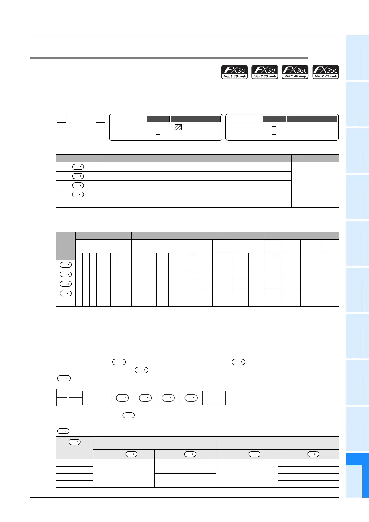
1. Instruction format
2. Set data
*1. Ch2 is not available in 14-point and 24-point type FX3G PLC.
3. Applicable devices
S: This function is supported only in FX3U/FX3UC PLCs.
Explanation of function and operation
→ For detailed explanation of the instruction, refer to the Data Communication Edition manual.
1. 16-bit operation (IVMC)
This instruction executes multiple commands of an inverter connected to a communication port n whose station
number is specified in . Specify the send/receive data type using , the head device which stores data to
be written to the inverter using , and the head device which stores values to be read from the inverter using
.
2. Send/recive data type
The table below shows valid send data 1 and 2 and receive data 1 and 2 specified by the send/receive data type
.
Operand Type Description Data Type
Inverter station number (K0 to K31)
16-bit binary
Multiple instructions for inverter: Send/receive data type specification
Head device which stores data to be written to the inverter (Occupies 2 points.)
Head device which stores values to be read from the inverter (Occupies 2 points.)
n
Channel to be used (K1: ch1, K2: ch2)
*1
Oper-
and
Type
Bit Devices Word Devices Others
System User Digit Specification System User
Special
Unit
Index
Con-
stant
Real
Number
Charac-
ter String
Pointer
XYMTCSD
.b KnX KnY KnM KnS T C D R
U\G
V Z Modify K H E "
"P
33 S 333
33 S 333
33 S 3
33 S 3
n 33
Send/recive
data type
Send data
(Write contents to Inverter)
Recive data
(Read contents from Inverter)
Data 1 ( ) Data 2 ( +1) Data 1 ( ) Data 2 ( +1)
H0000
Run command (expansion)
Set frequency (RAM)
Inverter status monitor
(expansion)
Output frequency (speed)
H0001 Special monitor
H0010
Set frequency
(RAM, EEPROM)
Output frequency (speed)
H0011 Special monitor
FNC 275
IVMC
16-bit Instruction
11 steps
IVMC
Continuous
Operation
Mnemonic
Operation Condition
32-bit Instruction
Mnemonic
Operation Condition
S
1
S
2
S
3
D
S
1
S
2
S
3
D
S
1
S
2
S
3
D
Command
input
FNC275
IVMC
S
1
S
2
S
3
n
D
S
2
S
2
S
2
S
3
S
3
D D

 Loading...


