397
FX3G/FX3U/FX3GC/FX3UC Series
Programming Manual - Basic & Applied Instruction Edition
14 Handy Instruction – FNC 60 to FNC 69
14.3 FNC 62 – ABSD / Absolute Drum Sequencer
11
FNC30-FNC39
Rotation and
Shift
12
FNC40-FNC49
Data Operation
13
FNC50-FNC59
High-Speed
Processing
14
FMC60-FNC69
Handy
Instruction
15
FNC70-FNC79
External FX I/O
Device
16
FNC80-FNC89
External FX
Device
17
FNC100-FNC109
Data
Transfer 2
18
FNC110-FNC139
Floating Point
19
FNC140-FNC149
Data
Operation 2
20
FNC150-FNC159
Positioning
Control
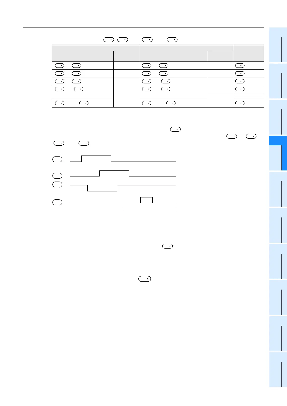
1) Write the following data to [ , +1] to [ +4n-2, +4n-1] in advance using a transfer instruction:
For example, store the 32-bit rising point data to devices having an even device number, and store the 32-bit
falling data to devices having an odd device number.
When the command input is set to ON, "n" points starting from change as shown below.
Each rising point/falling point can be changed respectively by overwriting the data in [ +1, ] to
[ +4n-1, +4n-2].
Cautions
1. Specifying a high-speed counter (C235 to C255)
In DABSD instruction, a high seed counter can be specified as .
In this case, however, the output pattern contains response delay caused by the scan cycle with regard to the current
value of a counter.
When high responsitivity is required in FX3U/FX3UC PLCs, use the table high-speed comparison function offered by
the HSZ instruction, or use the HSCT instruction.
2. When specifying digits of a bit device as
1) Device number
Specify a multiple of 16 (0, 16, 32, 64 ...).
2) Number of digits
- In ABSD instruction (16-bit operation): Only K4 is available.
- In DABSD instruction (32-bit operation): Only K8 is available.
3. Other cautions
• The value "n" determines the number of target outputs (1 ≤ n ≤ 64).
• Even if the command input is set to OFF, the ON/OFF status of outputs does not change.
Rising point Falling point
Target output
Data value
(example)
Data value
(example)
[+ 1,]
40
[ + 3, + 2]
140
[ + 5, + 4]
100
[ + 7, + 6]
200
+1
[ + 9, + 8]
160
[+ 11,+ 10]
60
+2
[ + 13, + 12]
240
[+ 15,+ 14]
280
+3
…
⎯
…
⎯
…
[ + 4n - 3, + 4n - 4] [ + 4n - 1, + 4n - 2] + n − 1
D
1
S
1
D
1
S
1
D
1
S
1
D
1
S
1
S
1
S
1
S
1
S
1
D
S
1
S
1
S
1
S
1
D
S
1
S
1
S
1
S
1
D
S
1
S
1
S
1
S
1
D
S
1
S
1
S
1
S
1
D
D
1
D
D
1
S
1
D
1
S
1
D
1
S
1
D
1
S
1
40 140
100 200
160
240 280
180
360
60
0
z
+3
+2
+1
D
D
D
D
D
1
S
2
D
1
S
1
 Loading...


