455
FX3G/FX3U/FX3GC/FX3UC Series
Programming Manual - Basic & Applied Instruction Edition
16 External FX Device – FNC 80 to FNC 89
16.3 FNC 82 – ASCI / Hexadecimal to ASCII Conversion
11
FNC30-FNC39
Rotation and
Shift
12
FNC40-FNC49
Data Operation
13
FNC50-FNC59
High-Speed
Processing
14
FMC60-FNC69
Handy
Instruction
15
FNC70-FNC79
External FX I/O
Device
16
FNC80-FNC89
External FX
Device
17
FNC100-FNC109
Data
Transfer 2
18
FNC110-FNC139
Floating Point
19
FNC140-FNC149
Data
Operation 2
20
FNC150-FNC159
Positioning
Control
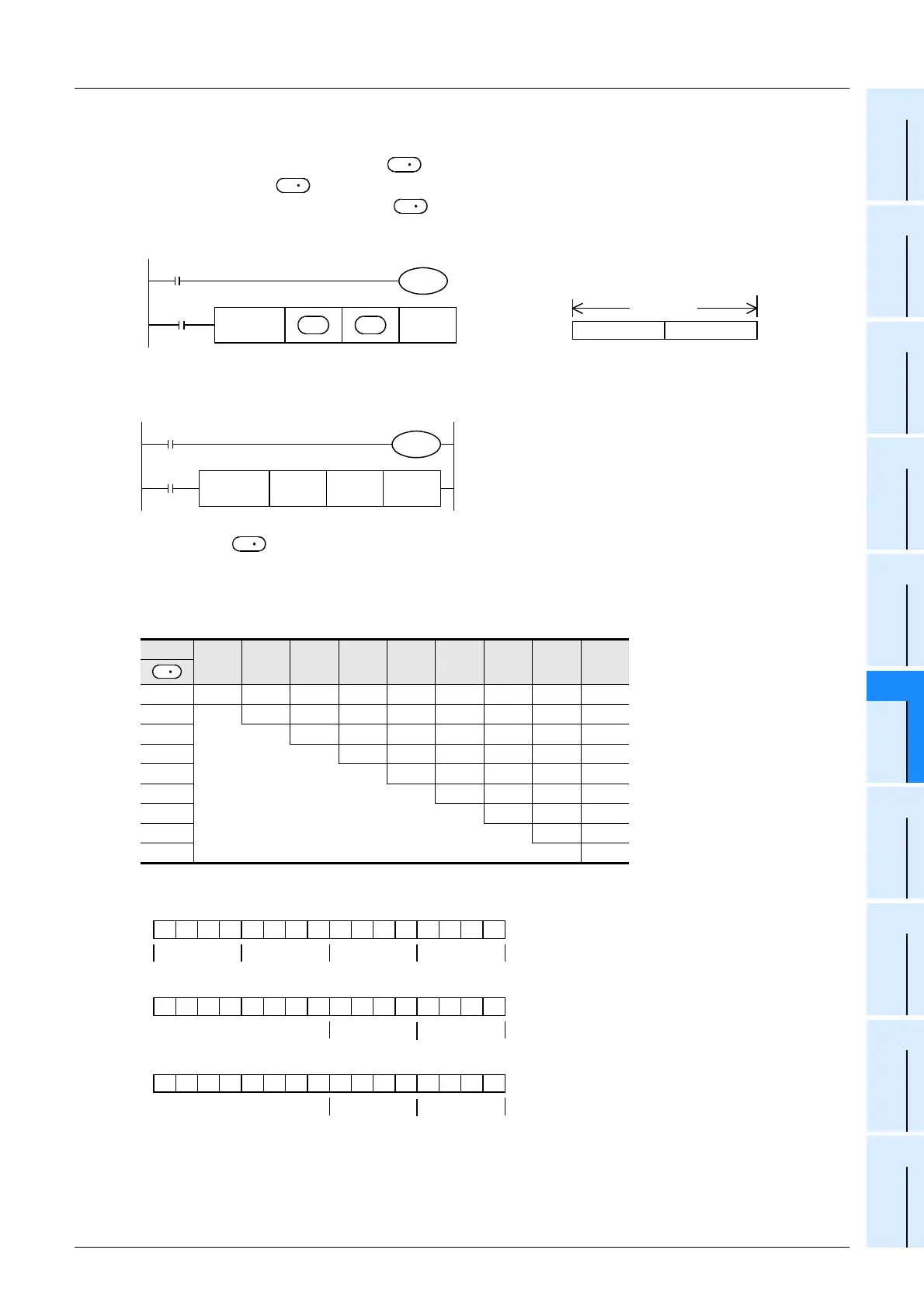
3. 8-bit conversion mode (while M8161 is ON)
(M8161 is used also for the RS, HEX, CCD and CRC instructions.)
Each digit of hexadecimal data stored in and later is converted into an ASCII code, and transferred to low-order
8 bits of each device and later. The number of digits (characters) to be converted is specified by "n". "0" is
stored in high-order 8 bits of each device and later.
M8161 is used also for the RS, HEX, CCD and CRC instructions. When using the 8-bit mode, set M8161 to normally
ON. M8161 is cleared when the PLC mode is changed from RUN to STOP.
Operation
In the following program, conversion is executed as follows:
Devices after
D100 = 0ABCH
D101 = 1234H
D102 = 5678H
Number of specified digits (characters) and conversion result
Bit configuration in the case of "n = K2"
• When outputting data in the BCD format for a printer, for example, it is necessary to convert binary data into BCD
data before executing this instruction.
n
K1 K2 K3 K4 K5 K6 K7 K8 K9
D 200 [C] [B] [A] [0] [4] [3] [2] [1] [8]
D 201 [C] [B] [A] [0] [4] [3] [2] [1]
D 202 [C] [B] [A] [0] [4] [3] [2]
D 203 [C] [B] [A] [0] [4] [3]
D 204 [C] [B] [A] [0] [4]
D 205 [C] [B] [A] [0]
D 206 Does not change [C] [B] [A]
D 207 [C] [B]
D 208 [C]
S
D
D
M8161
M8000
FNC 82
ASCI
nS
Command
input
D
8-bit mode
0
Low-order 8 bits
16 bits
When M8161 is set to ON, the 8-bit mode
is selected. The conversion processing is
executed as follows
Destination
M8161
M8000
FNC 82
ASCI
D100 D200 K4
X010
8-bit mode
S
D
0011110101010000
D 100 = 0ABCH
0ABC
0100001000000000
D200 = B
→
ASCII code = 42H
42
1100001000000000
D201 = C
→
ASCII code = 43H
43
ASCII codes
[0] = 30H [1] = 31H [5] = 35H
[A] = 41H [2] = 32H [6] = 36H
[B] = 42H [3] = 33H [7] = 37H
[C] = 43H [4] = 34H [8] = 38H

 Loading...


