542
FX3G/FX3U/FX3GC/FX3UC Series
Programming Manual - Basic & Applied Instruction Edition
20 Positioning Control – FNC150 to FNC159
20.1 FNC150 – DSZR / Dog Search Zero Return
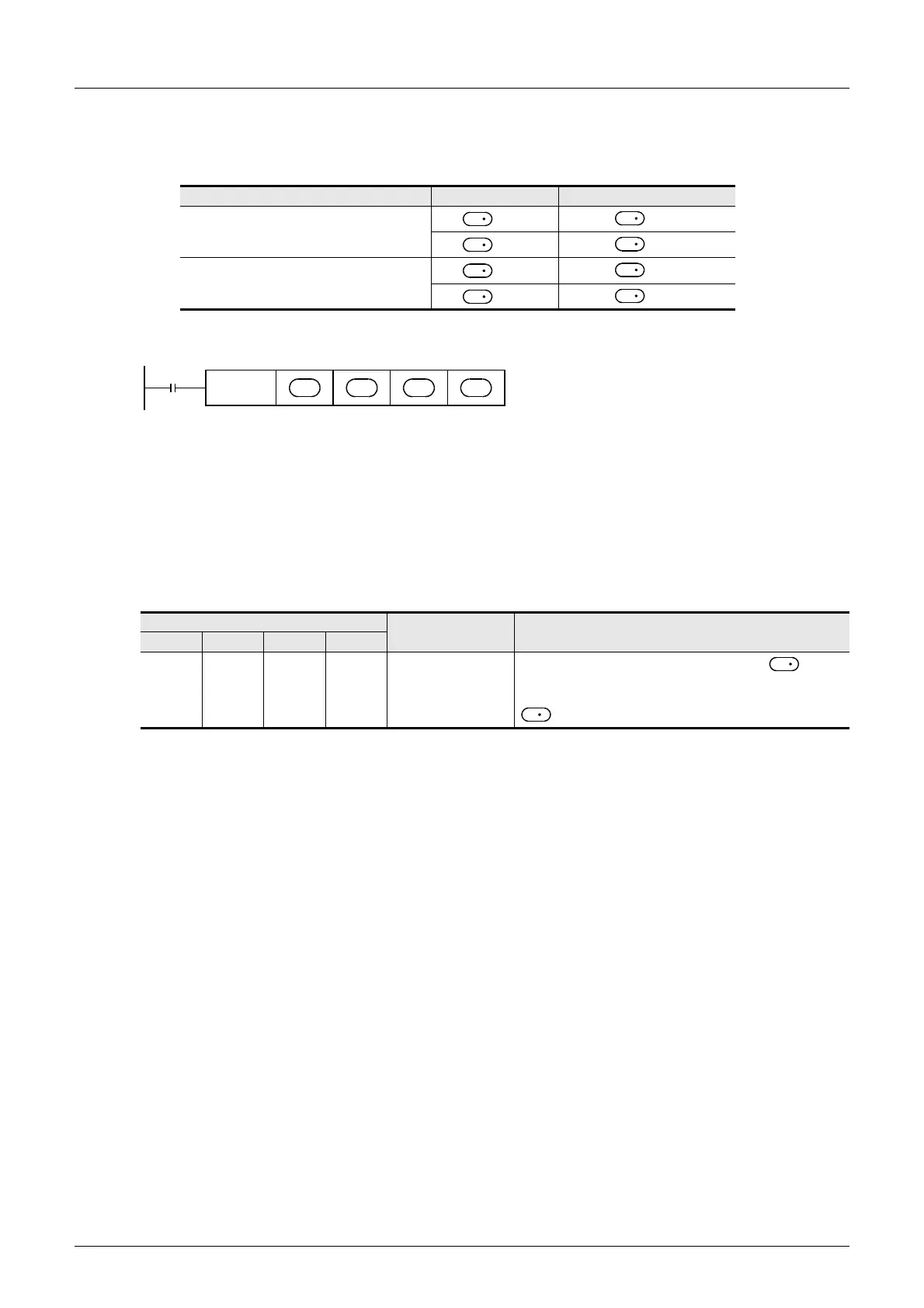
S4 : When using a special high-speed output adapter for the pulse output destination in an FX3U PLC, the rotation
direction signal must be used by the following table output.
When using a built-in transistor output for the pulse output destination in an FX
3G/FX3U/FX3GC/FX3UC PLCs, the
rotation direction signal must use transistor output.
Explanation of function and operation
Caution on writing during RUN
During RUN, avoid writing while the DSZR (FNC150) instruction is executed (that is, while a pulse is output).
Note that if writing is executed during RUN to a circuit block including the FNC150 instruction while pulses are output,
the PLC decelerates and stops pulse output.
Function change depending on the version
The function of FNC150 instruction is changed depending on the version as shown in the table below.
→ For explanation of the instruction and the contents of function change,
refer to the Positioning Control Edition.
Special high-speed output adapter No. Pulse output Rotation direction output
No. 1 (1st unit)
=Y000
=Y004
=Y001
=Y005
No. 2 (2nd unit)
=Y002
=Y006
=Y003
=Y007
Applicable version
Item Outline of function
FX3G FX3U FX3GC FX3UC
Ver. 1.00
or later
Ver. 2.20
or later
Ver. 1.40
or later
Ver. 2.20
or later
Clear signal output
destination
specification function
When a special auxiliary relay corresponding to is set to
ON, the clear signal output destination is changed to an output
number specified by a special data register corresponding to
.
D
1
D
2
D
1
D
2
D
1
D
2
D
1
D
2
Command
input
FNC150
DSZR
S
2
S
1
D
1
D
2
D
1
D

 Loading...


