832
FX3G/FX3U/FX3GC/FX3UC Series
Programming Manual - Basic & Applied Instruction Edition
37 Operation of Special Devices (M8000 -, D8000 -)
37.1 Special Device List (M8000 -, D8000 -)
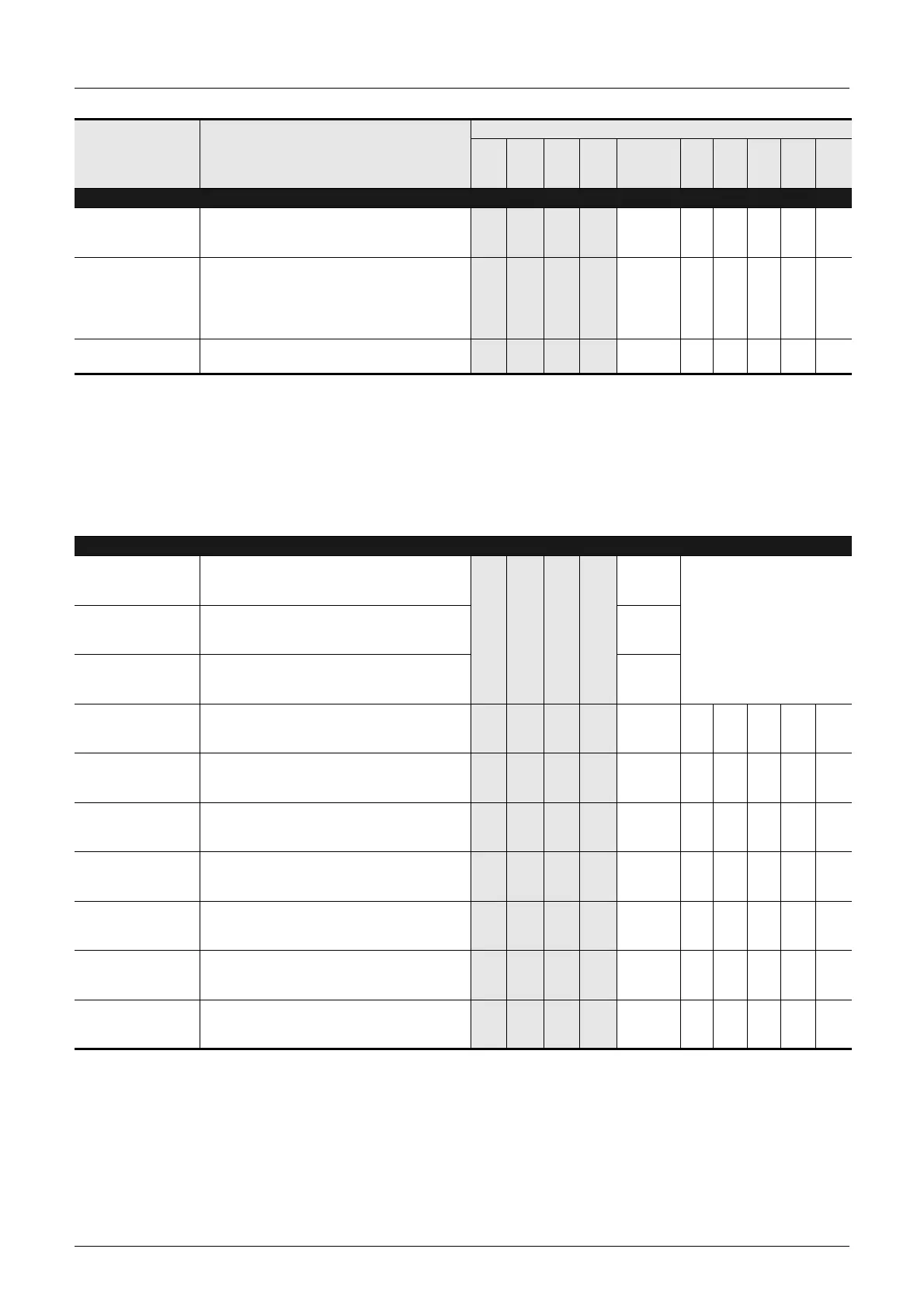
PLC Status
[D]8007
Momentary power
failure count
Operation frequency of M8007 is stored.
Cleared at power-off.
– – 3 3 M8007 – – 3 – 3
D8008
Power failure
detection
Default:
*1
•FX3U, FX2N PLCs:
10 ms (AC power supply type)
•FX2NC, FX3UC PLCs:
5 ms (DC power supply type)
– – 3 3 M8008 – – 3 – 3
[D]8009
24V DC failed device
Lowest input device number of the I/O extension
units in which 24 V DC power has failed
3 – 3 – M8009 – – 3 – 3
*1. The power failure detection time in FX2N and FX2NC PLCs is as follows.
-10ms for FX2N PLC used with a 100V AC power supply system. D8008 is set to 10ms by default.
- 100ms maximum for FX2N PLC used with a 200V AC power supply system. D8008 can be set ranging
from 10 to 100 ms.
-5ms for FX2N PLC used with a DC power supply type. Write "K-1" to D8008 for correction.
-5ms for FX2NC PLC used with a DC power supply type. System writes "K-1" to D8008 for correction. Do
not make any change in a sequence program.
-For FX3U and FX3UC PLCs, refer to Subsection 37.2.4.
Clock
[D]8010
Present scan time
Accumulated instruction-execution time from step 0
(in 0.1-ms units)
→Refer to Subsection 37.2.5.
3
Same
as on
the
right
3
Same
as on
the
right
3
Same
as on
the
right
3
Same
as on
the
right
–
3
Indicated value includes wait-
ing time of constant scan opera-
tion (when M8039 is activated).
[D]8011
Minimum scan time
Minimum value of scan time
(in 0.1-ms units)
→Refer to Subsection 37.2.5.
–
[D]8012
Maximum scan time
Maximum value of scan time
(in 0.1-ms units)
→Refer to Subsection 37.2.5.
–
D8013
Second data
0 to 59 seconds
(for real time clock)
→Refer to Subsection 37.2.7.
3 3 3 3 – 3333
3
*2
D8014
Minute data
0 to 59 minutes
(for real time clock)
→Refer to Subsection 37.2.7.
3 3 3 3 – 3333
3
*2
D8015
Hour data
0 to 23 hours
(for real time clock)
→Refer to Subsection 37.2.7.
3 3 3 3 – 3333
3
*2
D8016
Day data
1 to 31 days
(for real time clock)
→Refer to Subsection 37.2.7.
3 3 3 3 – 3333
3
*2
D8017
Month data
1 to 12 months
(for real time clock)
→Refer to Subsection 37.2.7.
3 3 3 3 – 3333
3
*2
D8018
Year data
2 digits of year data (0 to 99)
(for real time clock)
→Refer to Subsection 37.2.7.
3 3 3 3 – 3333
3
*2
D8019
Day-of-the-week data
0 (Sunday) to 6 (Saturday)
(for real time clock)
→Refer to Subsection 37.2.7.
3 3 3 3 – 3333
3
*2
*2. A memory board having the real time clock function is required in FX2NC PLC.
Number and name Content of register
Applicable model
FX
3G
FX
3GC
FX
3U
FX
3UC
Correspond-
ing special
device
FX
1S
FX
1N
FX
2N
FX
1NC
FX
2NC
 Loading...


