E-14
4 Analog Output
4.1 Analog Output Procedures
FX
3G
/FX
3U
/FX
3UC
PLC User's Manual - Analog Control Edition
FX3U-4DA (4-channel Analog Output)
3 Creation of sequence program
Create the program as follows to output analog signals.
• While referring to step 2, set the output mode "H****".
• While referring to step 1, set the unit number in
- Program Example (For FX
3U, FX3UC Series PLCs)
*1
*1. Use the FROM and TO instructions in FX3G PLCs.
4 Transfer of sequence program and analog output signal check
1) Transfer the sequence program, and start the PLC.
2) Check that analog signals appropriate to the set output data are output.
→ If analog signals are not output correctly, refer to Chapter 9 "Troubleshooting."
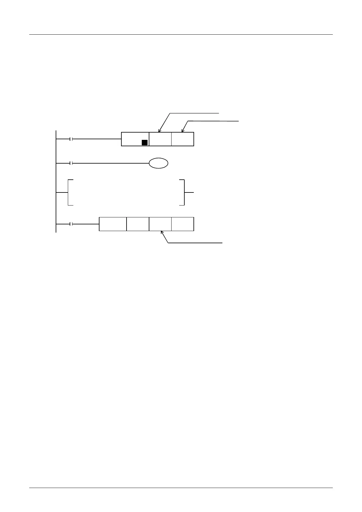
M8002
FNC 12
MOV
H**** U
\GO
P
M8000
K50
T0
T0
Specify the output mode (BFM #0) for channels
1 to 4.
Initial pulse
FNC 15
BMOV
D0 U
\G1 K4
Data (BMF #1 to 4) to be output to channels 1
to 4 are transferred from D0 to D3.
Output mode (step 2)
Unit number (step 1)
Unit number (step 1)
RUN monitor
Data to be output to channel 1 is written in D0.
Data to be output to channel 2 is written in D1.
Data to be output to channel 3 is written in D2.
Data to be output to channel 4 is written in D3.
Data to be output to channels 1 to 4 are stored in
D0 to D3.

 Loading...


