The enclosed kit is located behind the front service cover in indoor unit.
Assembly
■ It is recommended that indoor unit is installed in a room
with existing oor drainage, most suitably in a utility room
or boiler room.
■ The surface must be firm, preferably a concrete floor or
foundation. For wall mount unit, the surface must be f irm,
f lat and vertical, preferably a concrete wall.
■ Install indoor unit with its back to an outside wall, ideally
in a room where noise does not matter. If this is not
possible, avoid placing it against a wall behind a bedroom
or other room where noise may be a problem.
■ Floor standing indoor unit can be aligned using the
adjustable feet.
■ Route pipes so they are not fixed to an internal wall that
backs on to a bedroom or living room.
■
For HMA100V and HMA100VM, be sure that sufficinet
service space is provided as shown in following page.
■ For HMS140V be sure to connect a tank on HW port even if
HW application is not used.
■ For HMS140V
install tank unit and its pipings to indoor
unit indoors in order to avoid icing.
■
For HT30, MT300 and MT500, be sure that sufficinet
service space is provided as shown in following page.
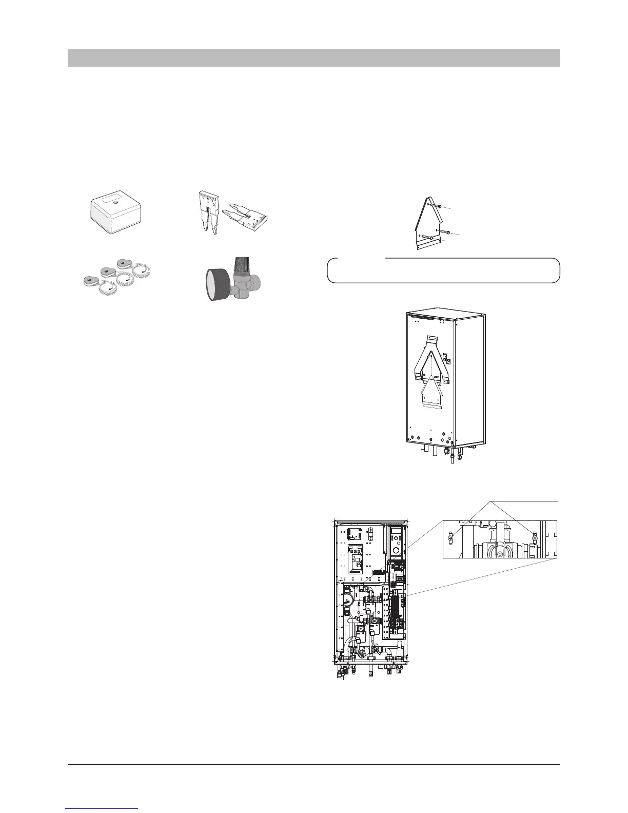
Hanging indoor unit on a wall (HMS140V)
1. Ensure the final product position keeps the required
clearance for installation and servicing.
2. Place the bracket attached onto the wall so that the hydrobox
is not tilted and fix it with 3 deck screws on the wall.
Choose appropriate size and material of screw according to
the material of the wall so that the indoor unit would not
fall down.
3. Hang indoor unit on bracket.
4. fix indoor unit on bracket with screws attached.
NOTE
Indoor unit weighs 60kg excluding water inside.
 Loading...


