2. INSTRUCTIONS
2 − 23
MELSEC-A
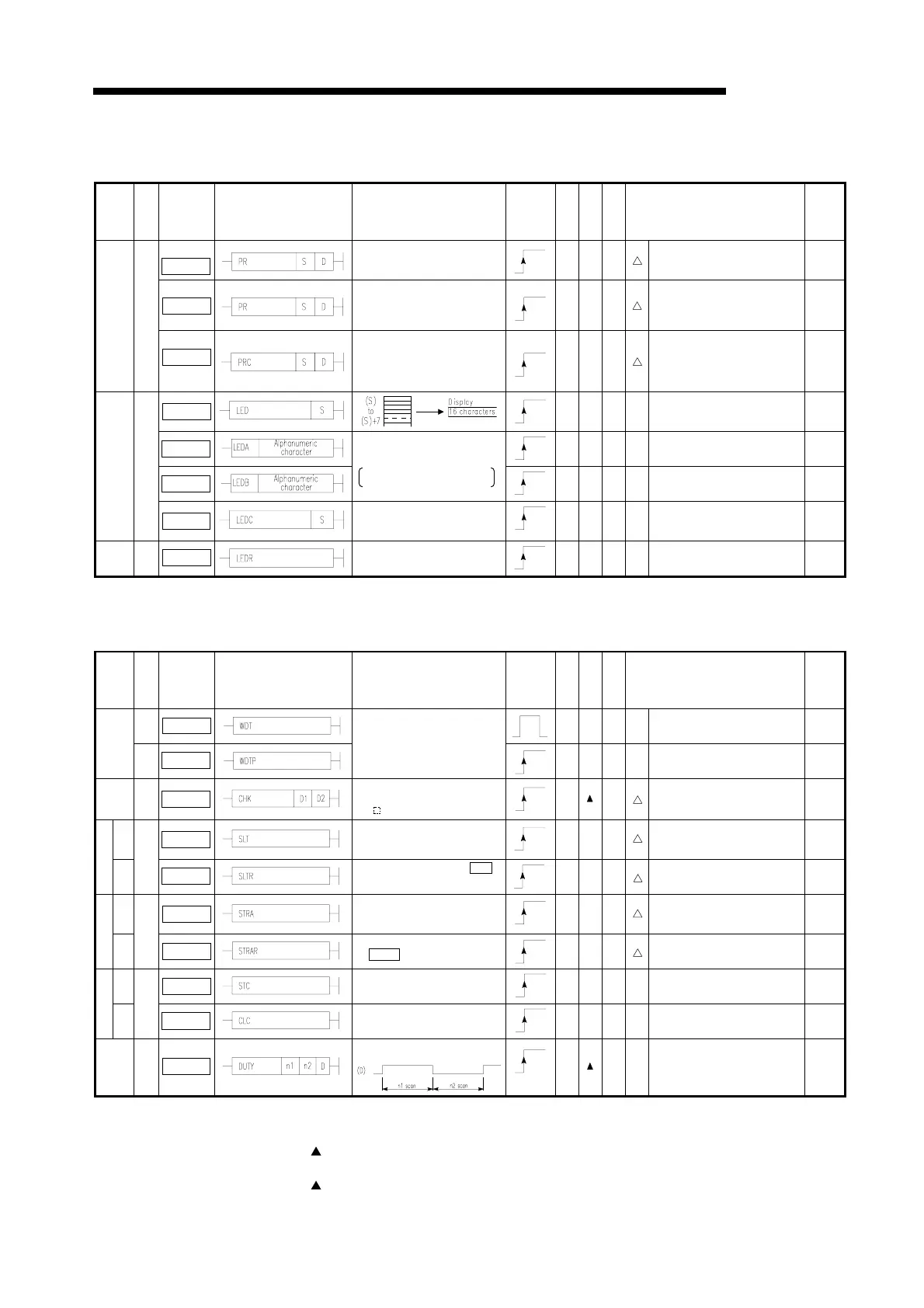
(9) Display instructions
Table 2.25 Display Instructions
Classi-
fication
Unit
Instruction
Symbol
Symbol Contents of Processing
Execu-
tion Con-
dition
Number
of steps
Index
Subset
Applicable CPU Page
PR
Outputs ASCII codes (16 charac-
ters) from the specified devices
(8 points) to the output module.
7
●
Not applicable to A2C and A52G. 7-106
PR
Outputs ASCII codes
sequentially from the specified
devices to the output module
until NUL (00H) is given.
7
●
Not applicable to An, A3V, A2C
and A52G.
7-106
ASCII
print
PRC
Converts the comment in the
specified device into ASCII code
and outputs to the output module.
The comment in device 1 may be
output.
7
●
Not applicable to A2C and A52G. 7-106
LED
3
●
Applicable to A3, A3N, A3H, A3M,
A3A, A3U, A4U, A73, A3V and A3N
board.
7-113
LEDA
13
Applicable to A3, A3N, A3H, A3M,
A73, A3V and A3N board.
7-116
LEDB
Indicates the specified alpha-
numeric characters on the display
LEDA: First 8 characters
LEDB: Second 8 characters
13
Applicable to A3, A3N, A3H, A3M,
A73, A3V and A3N board.
7-116
Display
LEDC
Displays the comment in
device, S.
3
●
Applicable to A3, A3N, A3H, A3M,
A3A, A3U, A4U, A73, A3V and A3N
board.
7-113
Display
reset
LEDR
Reset the display indication.
1
!
7-118
(10) Other instructions
Table 2.26 Other Instructions
Classi-
fication
Unit
Instruction
Symbol
Symbol Contents of Processing
Execu-
tion Con-
dition
Number
of steps
Index
Subset
Applicable CPU Page
WDT
1
!
7-122
WDT
reset
WDTP
WDT is reset in sequence
program
1
!
7-122
Failure
check
CHK
Failure→(D1):ON(D2):Failure NO
Normal→(D1):OFF(D2):0 When
A N is in the I/O direct mode.
5
Not applicable to A1FX. 7-124
Set SLT
At the condition set by parameter
setting, data are stored into
memory for status latch.
1 Not applicable to A1 and A1N. 7-131
Status latch
Re-
set
SLTR
Status latch is reset and SI.T
instruction is enabled
1 Not applicable to A1 and A1N. 7-131
set STRA
At the condition set by parameter
setting. sampling data are stored
into memory for status latch.
1 Not applicable to A1 and A1N. 7-133
Sampling trace
Re-
set
STRAR
Sampling trace is resumed.
( STRA instruction is enabled.)
1 Not applicable to A1 and A1N. 7-133
set STC
Carry flag contact(M9012)is
turned on.
1
!
7-135
Carry
Re-
set
1 bit
CLC
Carry flag contact(M9012)is
turned off.
1
!
7-135
Timing
clock
1 bit
DUTY
Timing clock shown below is
generated.
7
!
7-137
*1
*2
*1
*1: For the number of steps when extension devices are used or when index qualification is performed to
bit devices for AnA, A2AS, AnU, QCPU-A (A Mode) and A2USH board, refer to Section 3.8.1.
*2: The
mark in the Index column indicates that index qualification can be performed with the AnA,
A2AS, AnU, QCPU-A (A Mode) and A2USH board only.
*3: The
mark in the Subset column indicates that subset processing can be performed with the A3H,
A3M, AnA, A2AS, AnU, QCPU-A (A Mode) and A2USHboard only.
*2

 Loading...


