4. INSTRUCTION FORMAT
4 − 1
MELSEC-A
4. INSTRUCTION FORMAT
The explanations of instructions given in the following sections use the format
described in this section.
Available Device
Bit device Word (16-bit) device Constant Pointer
Level
X Y M L S B F T C D W R A0 A1 Z V K H P I N
M9012 (M9010, M9011)
(D) O O O O O
n O O
O O
*1: For the number of steps when A ACPU is used, refer to Section 3.8.1
*2: Subset processing can be used with A3HCPU, A3MCPU and A ACPU only
A1S An
AnN
AnN-F
A3H
A3M
A3V
AnA
AnA-F
AnU A0J2H A2C A73
A3N
board
Applicable
CPU
O O O O O O O O O X O
Remark
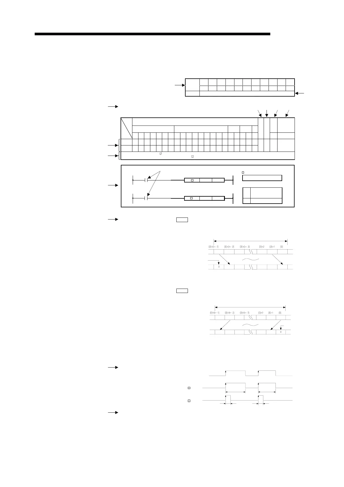
7.3.3 n-word data 1-word right shift, leftshif
(DSFR, DSFRP, DSFL, DSFLP)
(D)
Head number of device
which stores data to be
shifted
n Number of shifts
Setting data
DSFR, DSFL
Indicates the instruction s
mbol.
Shift commands
(D)
n
(D) n
P
Functions DSFR
(1) Shifts the word devices of "n" points, which be
in with the device specified at D,
to the right by one bit.
(2) The highest bit changes to 0.
(3) For T/C, the present value (count value) is shifted. (The shift of set value cannot be
performed.)
DSFL
(1) Shifts the word devices of "n" points, which be
in with the device specified at (D), to
the left by one bit.
(2) The lowest bit changes to 0.
(3) In regards to T/C, the present value (count value) is shifted.
(The shift of set value cannot be performed.)
Execution Conditions
OFF
ON
Executed
per scan
Executed
only once
P
Shift commands
Executed
per scan
Executed
only once
Operation Error In the following case, operation error occurs and the error fla
turns on.
"n" is a negative value.
2)
3)
1)
4)
9)
10)
11)
12)
13)
8)
7)
6) 5)
Before execution
After execution
Shift ran
e
n
oints
0 is entered.
Before execution
After execution
Shift ran
e
n
oints
0 is
entered.
Index
Carry
fla
Error
flag

 Loading...


