3. INSTRUCTION STRUCTURE
3 − 14
MELSEC-A
3.8 Cautions on Using AnA, A2AS, AnU, QCPU-A (A Mode) and A2USH board
This section gives the cautions to be exercised when AnA, A2AS, AnU, QCPU-A (A
Mode) and A2USH board is used.
3.8.1 The number of steps used in instructions
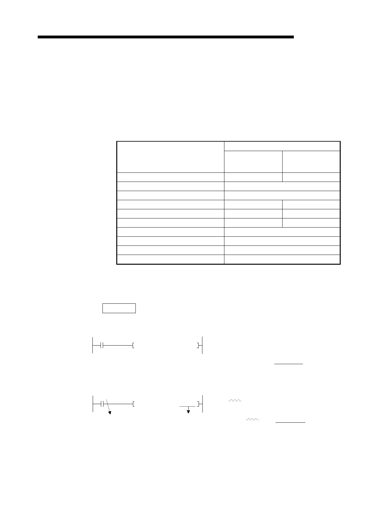
(1) The number of steps increases by one every time a device assigned as shown
below (device extended by AnA, A2AS, AnU, QCPU-A (A Mode) and A2USH
board) is used in each instruction.
Range
Device Name
AnA
A2AS, AnU,
QCPU-A (A Mode),
A2USH board
I/O X, Y - 800 to 1FFF
Internal relay M, L, S 2048 to 8191
Timer T 256 to 2047
Counter C 400 to FFF 400 to 1FFF
Link relay B 1024 to 6143 1024 to 8191
Data register D 400 to FFF 400 to 1FFF
Link register W 400 to FFF
Annunciator F 256 to 2047
Index register Z 1 to 6
Index register V 1 to 6
If index qualification is performed to the extension device with the extension
index register, the number of steps increases only one.
Example
• When basic devices only are used:
• When extension devices are used:
D0 W010……………. 5 steps
Total 6 steps
T0…………………….. 1step
T0
+ D0 W010
LD
+
T300……….…………1+1=2 steps
D0 W800………..5+1=6 steps
Total 8 steps
Extension device Extension device
T300
+ D0 W800
LD
+

 Loading...


