5. SEQUENCE INSTRUCTIONS
5 − 14
MELSEC-A
5.3 Output Instructions
5.3.1 Bit device, timer, counter output
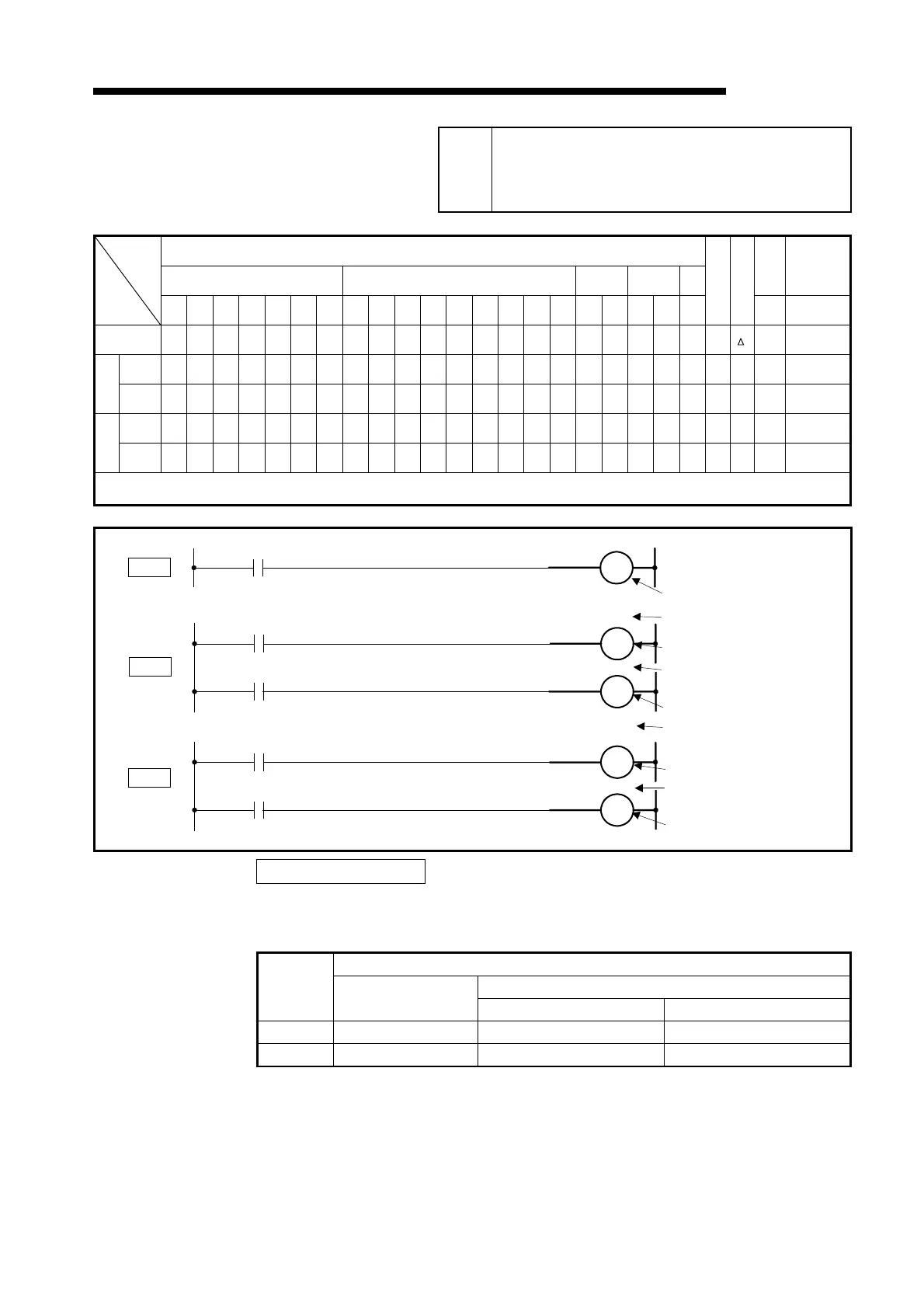
(OUT)
Available Device
Bit device Word (16-bit) device Constant Pointer
Level
Carry
flag
Error
flag
X Y M L S B F T C D W R A0 A1 Z V K H P I N
Digit specification
Index
M9012 (M9010, M9011)
Bit device
O O O O O O
Device
O
Set Value
O O
Device
O
Set value
O O
*1: Index qualification can be used AnA, A2AS, AnU, QCPU-A (A Mode) and A2USH board only.
*2: If extension timers or counters are used with the AnA, A2AS, AnU, QCPU-A (A Mode) and A2USH board, refer to Section 3.8.3.
Functions OUT (Y, M, L, S, B, F)
(1) This instruction outputs the operation result for the elements pereceding the
OUT instruction.
OUT Instruction
Contact
Operation
Result
Coil
NO contact NC contact
OFF OFF Non-continuity Continuity
ON ON Continuity Non-continuity
Applicable
CPU
All CPUs
*2
*2
*2
*2
*
OUT
OUT
OUT
(Y, M, L, S, B, F)
(T)
(C)
Y35
Device number
T0
Set value (Content of data
resister. 1 to 32767 are valid.)
K50
Set value (1 to 32767 are valid.)
Set value (1to 32767 are valid.)
Device number
T0 to 255
D10
Device number (T0 to 255)
T0
K50
Set value (Content of data
resister. 1 to 32767 are valid.)
C0
Device number (C0 to 255)
D10
C1
Device number (C0 to 255)

 Loading...


