7. APPLICATION INSTRUCTIONS
7 − 49
MELSEC-A
7.4.4 7 segment decode
(SEG)
The SEG instruction for the CPUs except An changes in function depending on the
status of special relay M9052, as follows.
When M9052 is ON: Partial refresh
(See Section 6.7.3 for details.)
When M9052 is OFF: 7-segment decode
Available Device
Bit device Word (16-bit) device Constant Pointer
Level
Carry
flag
Error
flag
X Y M L S B F T C D W R A0 A1 Z V K H P I N
Digit specification
Index
M9012 (M9010, M9011)
(S) O O O O O O O O O O O O O O O O O O K1
(D) O O O O O O O O O O O O O O O
O
*1: If the CPUs other than A3H, A3M, AnA, A2AS,AnU, QCPU-A (A Mode) and A2USH board are used, digit specification is ignored and 8-bit (2 digits) data
is always output.
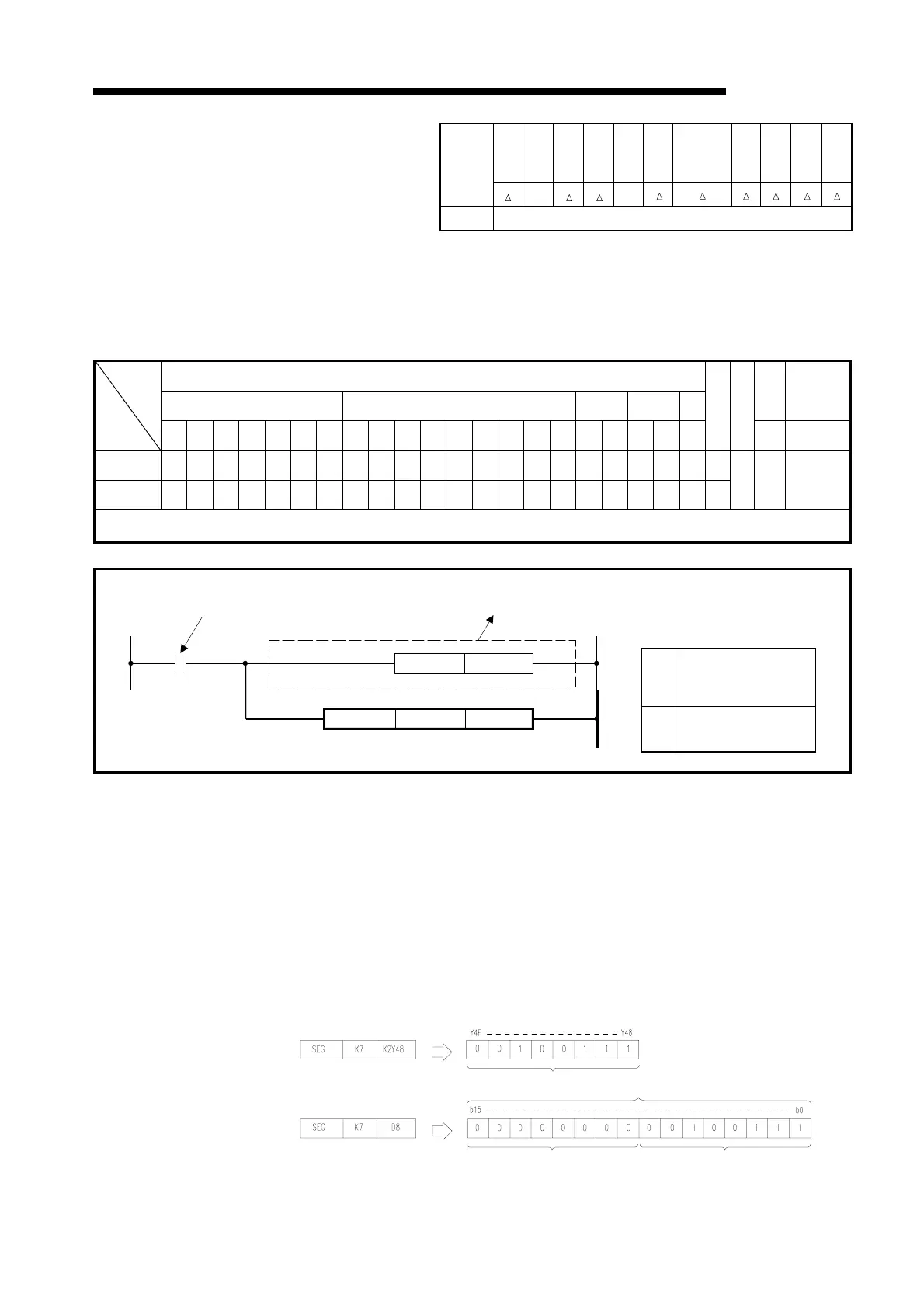
Functions (1) Decodes the data of 0 to F specified at the lower four bits of (S) to seven-
segment display data and stores the result to (D).
(2) When the device is a bit device (Y, M, L, S, B, F), indicates the head number of
device which will store the seven-segment display data. When the device is a
word device (T, C, D, R, A0, A1, Z, V), indicates the device number which will
store the seven-segment display data.
(3) The data is stored into the bit device and word device as shown below.
AnS
AnN
AnSH
An A1FX
A3H
A3M
A3V AnA
AnU, A2AS
A2USH-S1
A2USH board
QCPU-A
(A Mode)
A0J2H
A2C
A52G
A73
A3N
boad
Applicable
CPU
O X
Remark
* Valid only when special relay M9052 is OFF.
* * * * * * * * *
K1
to *1
K4
Decode command Not necessary for the An.
(S) (D)
M9052RST
SEG
(S)
Data to be decoded or
head number of device
which stores data to be
decoded
(D)
Head number of device
which will store decode
result.
Setting data
Before execution
Bit device
After execution
Word device
8
oints
Upper 8 bits are set to 0.
7-segment display data is
stored into lower 8 bits.
D8

 Loading...


