5. SEQUENCE INSTRUCTIONS
5 − 20
MELSEC-A
(3) The functions of RST (D, W, R, A0, A1, Z, V) are the same as those of the
following circuit.
If the annunciator relay (F ) is turned ON/OFF, display contents of LED indicators
and ERROR LEDs on the CPU module and contents of special registers change. For
details, refer to the ACPU Programming Manual (Fundamentals).
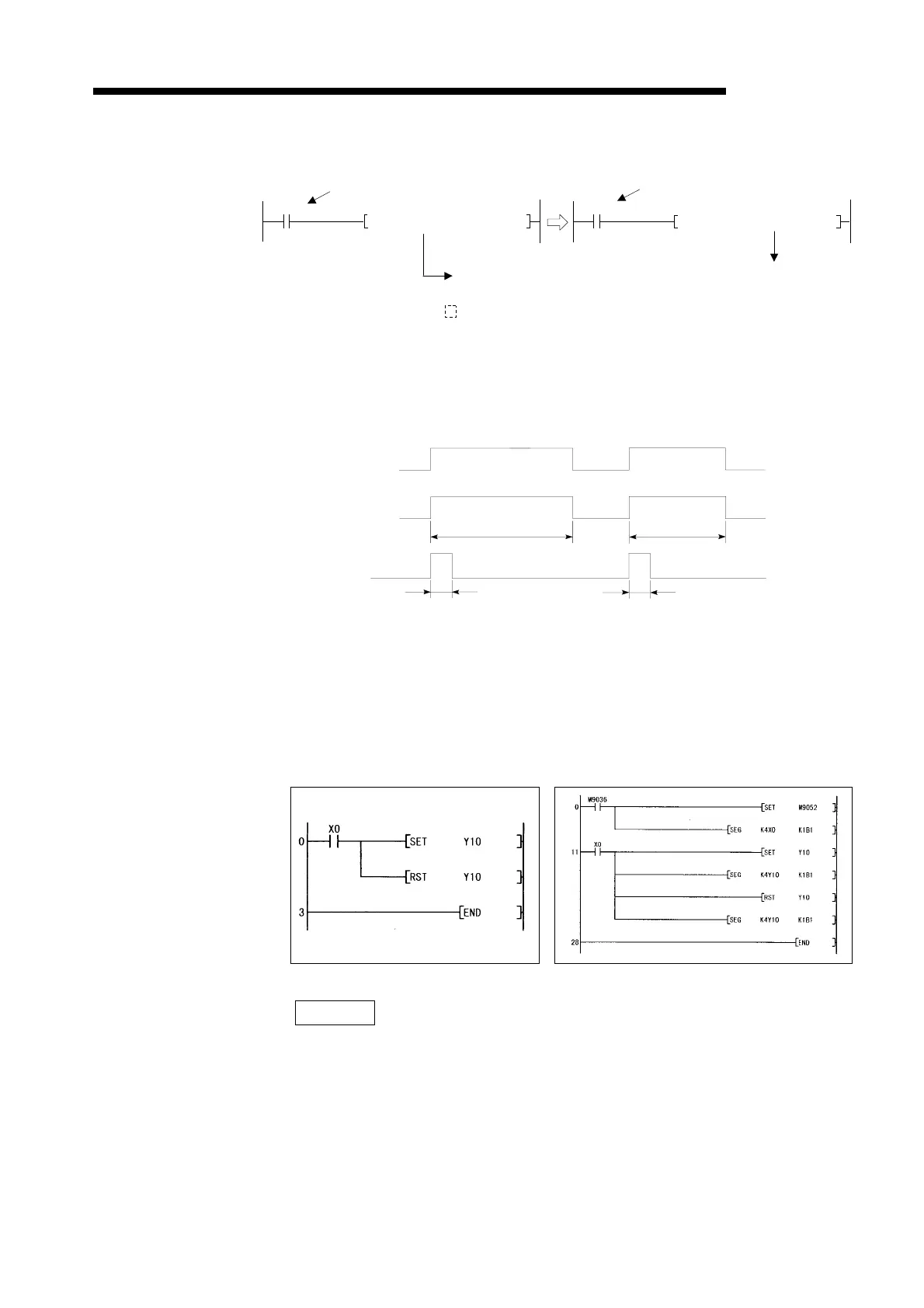
Execution (1) The SET, RST instructions are executed on the following conditions:
Conditions
(2) SET, RST instructions
In refresh mode, the SET/RST instructions cannot be used in a program which
outputs a pulse signal during one scan. In this case, output (Y) must be
changed to direct mode or add the partial refresh command as shown below.
REMARK
The number of steps is 3 when any of the following devices is used:
SET instruction Special relay (M)
Link relay (B)
Annunciator (F)
RST instruction Special relay (M)
Word devices (All)
RST input
RST input
Device number
(D, W, R, A0, A1, Z, V)
Device numbe
D, W, R, A0, A1, Z, V
X010
RST D50
X010
K
MOV 0 D50
Direct mode Refresh mode
SET, RST
instruction
SET, RST (Y, M, L, S, B)
SET, RST (F)
Executed every scan
Executed
ever scan
Executed
only once
Executed only
once
ON
OFF
 Loading...


