Designation
by
numeric switch
When the
PARA
number 14 setting is
"1
'I,
"2",
"5", "6", "9", "1
O",
"1
3", or
"1
4", block numbers
of
100
divisions or less are designated as
KO to K99.
It
is
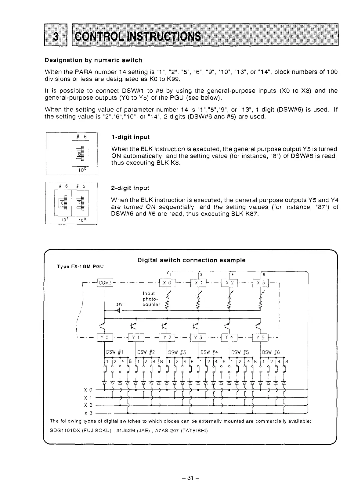
possible to connect DSW#1 to
#6
by using the general-purpose inputs (X0 to X3) and the
general-purpose outputs (YO to Y5)
of
the
PGU
(see below).
When the setting value of parameter number 14 is "1","5","9", or "1 3",
1
digit (DSW#6)
is
used.
If
the setting value is "2","6","10", or "14", 2 digits (DSW#6 and
#5)
are used.
1
-digit input
When the BLK instruction
is
executed, the general purpose output
Y5
is
turned
ON automatically, and the setting value (for instance, "8")
of
DSW#6 is read,
thus executing BLK K8.
1m
10'
100
2-digit input
When the BLK instruction is executed, the general purpose outputs Y5 and Y4
are turned
ON sequentially, and the setting values (for instance,
"87")
of
DSW#6 and #5 are read, thus executing BLK K87.
Digital switch connection example
Type
FX-1GM
PGU
I
Input
photo-
j
24v
coupler
I
I
\-.-
x0
x1
x2
-
-
x3
r'
f
I
l
f
J
The following types
of
digital switches
to
which diodes can be externally mounted are commercially available:
SDG4101
DX
(FUJISOKU)
,
31
J52M (JAE)
,
A7AS-207 (TATEISHI)
-
31
-
 Loading...


