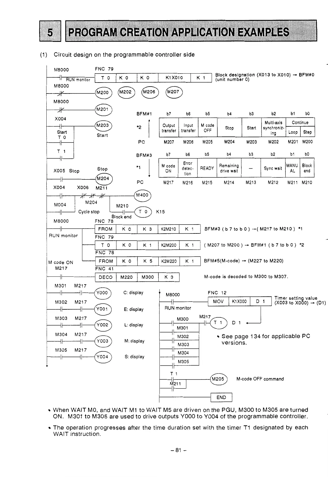
(1)
Circuit design on the programmable controller side
L
c
M8000
FNC 79
+I
RUN
monitor
I
T
0
I
K
0
I
K
0
I
K1 X01
0
[
'
]
(unit number
0)
Block designation (X01
3
to
X01
0)
-
BFM#O
M8000
M8000
BFM#l
b7 b6 b5 b4 b3 b2
bl
bO
Multi-axis
transfer transfer
OFF
Continue
synchroniz-
Start
Stop
Output
Input
'Ode
X004
ing
PC
M207 M206
M205
M204 M203 M202 M201 M200
Step
LOOP
Start
BFM#3
b7 b6 b5 b4 b3 b2
bl bO
MANU
PC
M217 M216 M215 M214 M213 M212 M211 M210
end
drive
wait
Block
M
code
ON
detec-
READY
tion
Error
AL
Sync wait
-
Remaining
X005 Stop
+I
Cycle stop
+I
BFM#3 (b7 to bo)
--(
M217
to
M210) *1
Maooo
FNC 78
RUN
monitor FNC 79
-
(
M207
to
M200
)
-
BFM#1
(
b 7 to b
0
)
*2
FNC 78
M
code ON BFM#S(M-code)
-.
(M227
to
M220)
M217 FNC 41
+I
M-code is decoded
to
M300
to
M307.
K 3
M300 M220 DECO
+Hl---Gh
M301 M217
W
M302 M217
+HI*
----IF---+*
M303
M217
M304 M217
M305
M217
C: display FNC 12
-1
I
KIXooo
I
1
(X003
to
XOOO)
+
(Dl)
Timer setting value
E: display
See page 134 for applicable
PC
M:
display
versions.
S:
display
M305
pi+(@
M-code OFF command
END
When WAIT MO, and WAIT M1 to WAIT M5 are driven on the
PGU,
M300 to M305 are turned
ON. M301
to
M305 are used
to
drive outputs
YO00
to
YO04
of the programmable controller.
The operation progresses after the time duration set with the timer T1 designated by each
-
WAIT instruction.
-81
-
 Loading...


