App-256
*1 The information of the host CPU module is stored.
SD1588
Reason(s) for
system
switching
Reason(s)
for
system
switching
that
occurred in
host station
Stores the reason(s) for system switching on the host system. The
following values are stored corresponding to the methods for
system switching:
This register is initialized with zero (0) stored when the system is
powered on from off or is reset.
•0: Initial value (control system has never been switched)
•1: Power off, Reset, H/W failure, WDT error
•2: CPU stop error (except WDT)
•3: System switching request from network module
•16: System switching dedicated instruction
•17: System switching request from a programming tool
S
(when
condition
occurs)
QnPRH
SD1589
Reason(s) for
system
switching
failure
conditions
Reason(s)
for system
switching
failure No
• If a system switching is failed, any of the following value is
stored in this register.
•0: System switching complete (default)
•1: Tracking cable is not connected, tracking cable failure, or
internal circuit failure
•2: H/W failure, power-off, reset, watchdog timer error on the
standby system
•3: H/W failure, power-off, reset, WDT error on the control
system
•4: Preparing tracking communication
•5: Communication timeout
•6: Stop error on the standby system (except for watchdog timer
error)
•7: Operation differs between both systems (detected only in the
back up mode)
•8: During memory copy from control system to standby system
•9: Performing program online change
•10: Detecting a failure of network module on the standby
system
•11: System is being switched
• Resets to "0" when host system is powered on.
• Zero is stored in this register upon completion of system
switching.
S
(when system
is switched)
SD1590
Network
module head
address,
which
requested
system
switching
Network
module head
address,
which
requested
system
switching
• When system switching is requested from a network module in
the host system, the bit corresponding to the module that
received the request turns on.
• The system turns off the bit after the error is removed by a user.
• For the number for modules where system switching is
requested from a network module in other system, refer to
SD1690.
S
(Error/Status
change)
New
SD1595
Memory copy
target I/O
number
Memory
copy target I/
O number
• Before SM1595 is turned from off to on, the I/O No. of the
memory copy destination (Standby system CPU module: 3D1
H
)
is stored in this register.
U
SD1596
Memory copy
status
Memory
copy status
• Stores the execution result of Memory copy function.
•0: Memory copy is complete
•4241
H
: Standby system power supply off
•4242
H
: Tracking cable is disconnected or is damaged
•4247
H
: Memory copy is being executed
•4248
H
: Unsupported memory copy destination I/O number
S
(Status
change)
Number Name Meaning Explanation
Set by
(When Set)
Corres-
ponding
ACPU
D9
Corres-
ponding
CPU
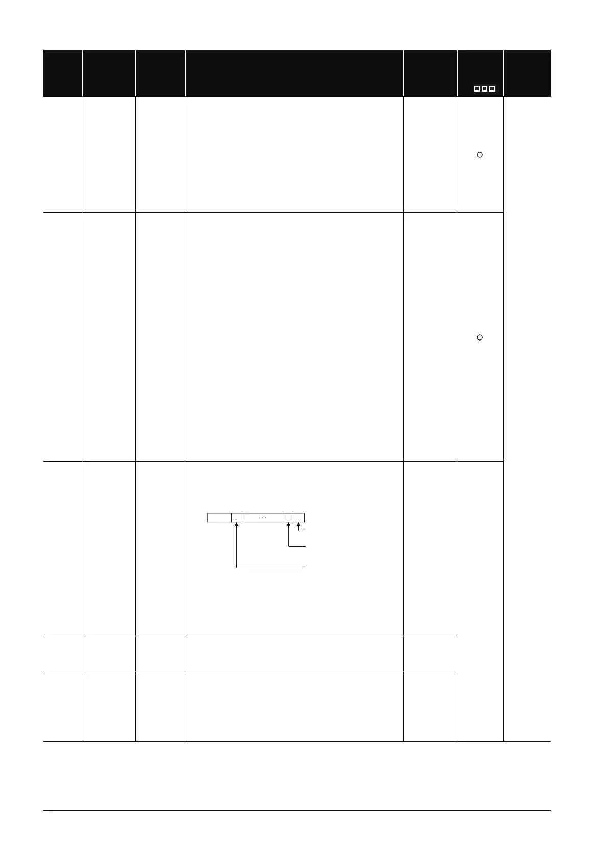
b1 b0b15 b11
0
0/10/10
SD1590
Module 0:
Module 1:
Module11:
Each bit
0:OFF
1:ON
to
CPU module is invalid
as it is 2-slot model
Module on right side of
CPU module
Module at rightmost
end of 12-slot base
(Q312B)
to to

 Loading...


