App-257
8
8
8
8
A
6
7
8
Appendix4 SPECIAL REGISTER LIST
(16) Redundant system (other system CPU information
*1
)
The special register (SD1600 to SD1650) is valid when the redundant system is in backup mode and is invalid in
separate mode. The special register (SD1651 to SD1690) is valid when the redundant system is in backup mode
or in separate mode. All bits in SD1600 to SD1690 are set to "0" for stand-alone systems.
Number Name Meaning Explanation
Set by
(When Set)
Corres-
ponding
ACPU
SD
*2
Corres-
ponding
CPU
SD1600
System error
information
System error
information
• If an error is detected by the error check for redundant
system, the corresponding bit shown below turns on. That bit
turns OFF when the error is cleared after that.
• If any of b0, b1, b2 and b15 is on, the other bits are off.
• In the debug mode, b0, b1, b2 and b15 are all off.
S
(Every END
processing)
-
QnPRH
SD1601
System
switching
results
System
switching
results
Reason(s) for system switching is stored.
• When a system is switched, the reason for system switching
is stored in SD1601 of both systems.
• This register is initialized with zero (0) stored when the
system is powered on from off or is reset.
• The following shows the values stored in this register.
•0: Initial value (control system has never been switched)
•1: Power-off, reset, H/W failure, or watchdog timer error
*1
•2: Stop error (except for watchdog timer error)
•3: A system switching request from network module
•16: Control system switching instruction
•17: System switching request from a programming tool
*1: When the system is switched upon the power-off or reset of
the control system, "1" is not stored in SD1601 of the new
standby system.
S
(when system
is switched)
SD1602
System
switching
dedicated
instruction
parameter
System
switching
dedicated
instruction
parameter
• This register stores the argument to the instruction when a
system is switched by the SP.CONTSW instruction.(The
argument for the SP.CONTSW instruction is stored in
SD1602 of both systems upon system switching.)
• SD1602 is only valid when "16" is stored in SD1601.
• SD1602 is updated only when a system is switched by the
control system switching instruction.
SD1610
Other system
diagnostic
error
Diagnostic
error code
• This register stores an error code for the error occurred on
other system.
• The value in SD0 of the CPU module on other system is
reflected.
S
(Every END
processing)
SD0
SD1611 Other system
diagnostic
error
occurrence
time
Diagnostic
error
occurrence
time
• Stores the date and time when diagnostics error occurred
corresponding to error code stored in SD1610.
• Data format is the same as SD1 to SD3.
• The values in SD1 to SD03 of the CPU module on other
system are reflected.
SD1 to
SD3
SD1612
SD1613
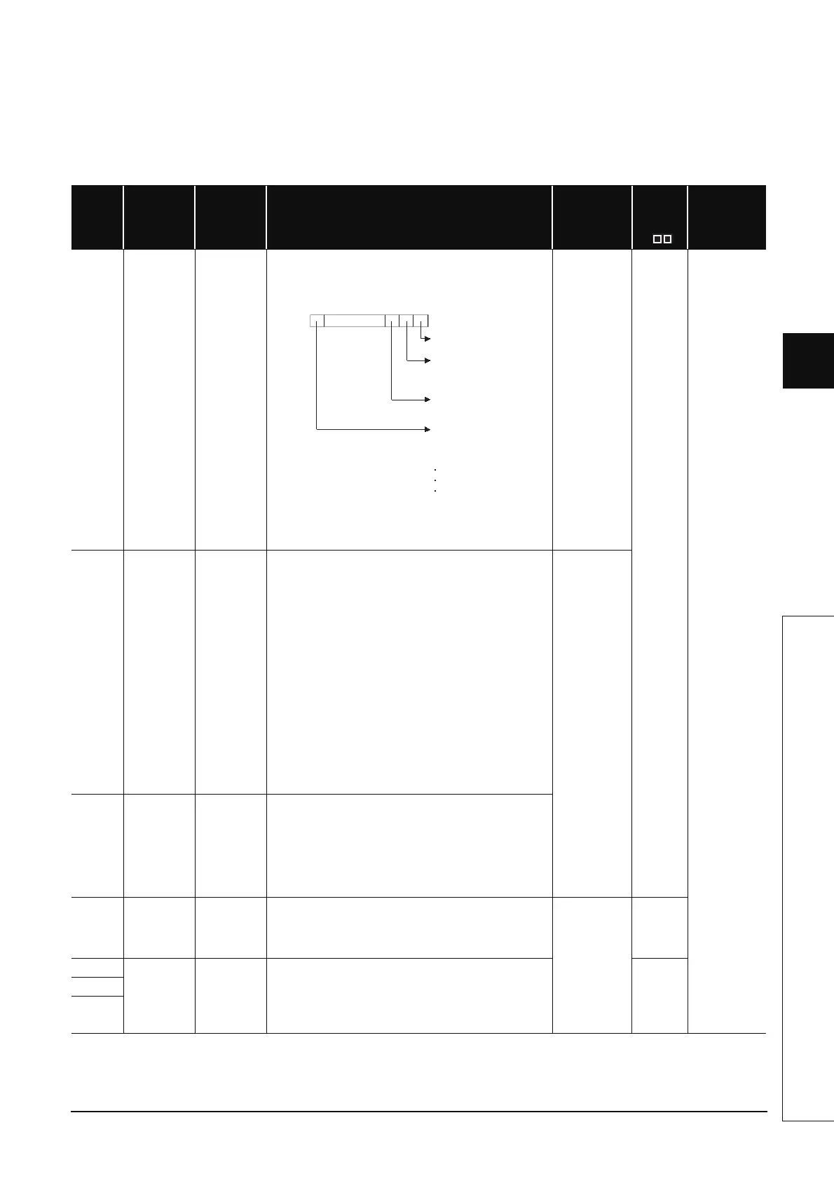
b1 b0b15 b2
Fixed to 0
SD1600
Each bit
0: OFF
1: ON
Tracking cable is not
connected or damaged
Power-OFF, reset,
watchdog timer error or
hardware failure occurred
in other system
Other system stop error
(except watchdog timer
error)
Bit turns on when faili
ng to
connect with other system.
The following causes are
shown below:
Tracking H/W failure
Host system WDT error
Cannot recognize other
system therefore causing
error

 Loading...


