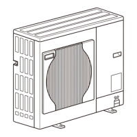
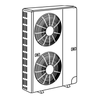
[5-1 Dipswitch Functions and Factory Settings ]
- 78 -
HWE12050 GB
1) To change the settings, set SW6-10 to ON, set SW4, and press and hold SWP01 for 2 seconds or longer (OFFON).
LED3 will light up when the switch setting is ON, and lights off when OFF.
Use the LED3 display to confirm that the settings are properly made.
The settings will need to be set again when the control board is replaced. Write down the settings on the electrical wiring drawing label.
2) A: OC: Only the switch on OC needs to be set for the setting to be effective.
B: OC: The switches on both the OC and OS need to be set to the same seeing for the setting to be effective.
C: OC: The switches on both the OC and OS need to be set.
D: OC: The switch on either the OC or OS needs to be set.
3) For details, refer to the following page(s).[5-2-7 Defrost Operation Control](page 86)
4) The table below shows the combinations of the settings for items No. 964 and No. 982 and the target evaporating temperature setting that corresponds
to each combination.
5) Unless otherwise specified, leave the switch to OFF where indicated by "-," which may be set to OFF for a reason.
6) The settings that are configured with SW4 (SW6-10: ON) will automatically be stored on the indoor units that support the new function*. The stored
settings will automatically be restored when the outdoor unit control board is replaced.
If none of the connected indoor units supports the new function, no configuration information will be saved. If this is the case, manually record the
settings configuration on the control box panel.
*The new function is supported on most units that are manufactured in December of 2012 and later. Depending on the model, this function may be
added on later date. Ask your dealer for further details.
Switch Function
Function according to switch setting
Switch setting timing
Units that
require
switch
setting
(Note 2)
OFF (LED3 Unlit) ON (LED3 Lit)
SW4
SW6-10:
OFF
1-10
1:ON, 0:OFF
Self-diagnosis/operation
monitor
Refer to the following page(s). [9 LED Sta-
tus Indicators on the Outdoor Unit Circuit
Board](page 253)
Anytime after power on C
SW4
1-10
[0:OFF,
1:ON]
(Note 1)
SW6-10:ON
No.769 1000000011 Test run mode: ON/OFF Stops all ICs
Sends a test-run sig-
nal to all IC
Anytime after power on A
No.832 0000001011
Cumulative compressor
operation time deletion
Retained Cleared Anytime after power on (OFFON) C
No.896 0000000111
Clearance of error
history
OC Retained (IC/OC) Deleted (IC/OC)
Anytime after power on (OFFON) C
OS Retained (OS) Deleted (OS)
No.897 1000000111
High sensible heat opera-
tion setting
Normal control
High sensible heat
operation mode
Before power on A
No.912 0000100111 Pump down function Normal control
Pump down opera-
tion
After being energized and while the com-
pressor is stopped
A
No.913 1000100111 Forced defrost (Note 3) Normal control Forced defrost starts
10 minutes after the completion of de-
frost operation (OFFON) or 10 minutes
after compressor start-up (OFFON)
D
No.915 1100100111
Defrost start temperature
(Note 3)
EP200: -10°C [14°F]
EP250 - EP450:
-8°C [18°F]
-5°C [23°F] Anytime after power on B
No.916 0010100111
Defrost end temperature
(Note 3)
EP200, EP300,
EP350: 10°C [50°F]
EP400, EP450:
12°C [54°F]
EP250: 7°C [45°F]
5°C [41°F] Anytime after power on B
No.921 1001100111 Temperature unit display °C °F Anytime after power on C
No.922 0101100111
Refrigerant amount adjust-
ment
Normal control
Refrigerant amount
adjust mode
Anytime after power on (except during
initial startup/becomes ineffective 60
minutes after compressor started up.
A
No.932 0010010111 Heating backup Disabled Enabled Anytime after power on A
No.964 0010001111
Target evaporation tem-
perature setting
Depends on the setting combination with No.
982 (Note 4)
Anytime after power on A
No.972 0011001111
Automatic cooling/heating
mode (IC with the smallest
address)
Normal control
Automatic cooling/
heating mode
Before power on A
No.982 0110101111
Target evaporation tem-
perature setting
Depends on the setting combination with No.
964 (Note 4)
Anytime after power on A
Switch
No.982
OFF ON
No.964 OFF 0°C [32°F] -4°C [25°F]
ON -2°C [28°F] -15°C [5°F]
 Loading...
