4 - 28 4 - 28
MELSEC-Q
4 WHEN THE QCPU ACCESSES THE OTHER STATION PLC USING THE
DATA LINK INSTRUCTION
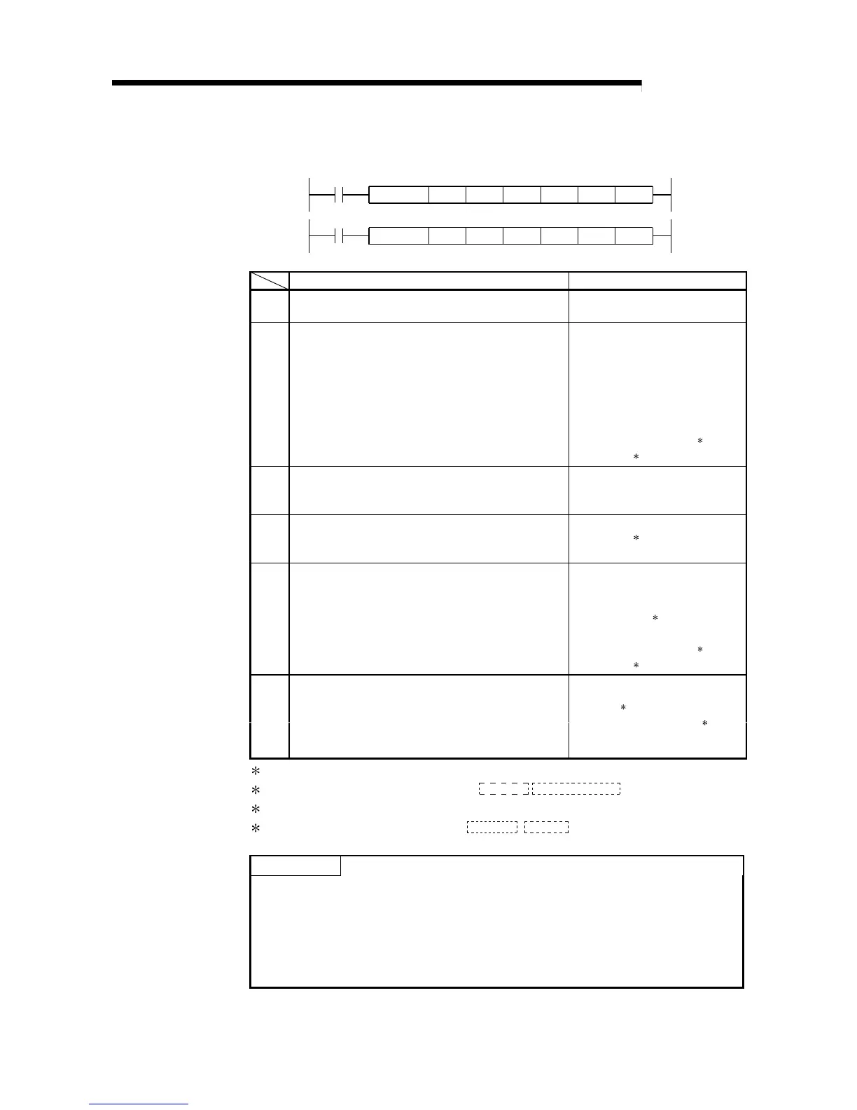
(b) ZNWR instruction
[Network number designation]
J.ZNWR
J: Execution
during ON
Jn
Write command
JP.ZNWR
J: Execution
during startup
Jn
Write command
n1
n1
n2
n2
(D1) (S) (D2)
(D1) (S) (D2)
Setting details Setting range
Jn
Target station network number
Designate the target station network number.
1 to 239
n1
Target station number
Designate the target station number.
1 to 64 (constant): Stations of station
number
81H to 89
H
: All stations of
group number
FF
H
: All stations on the
target network
number
Bit device digit designation
2
Word device
3
(D1)
Write data storage head device (target station)
Designate the head device of the target station that stores
the data to write.
T, C, D, W
(S)
Write data storage head device (local station)
Designate the head device of the local station which will
store the data to write.
Word device
3
n2
Write data length
Designate the number of data (words) to write.
When writing from Q/QnACPU
1 to 230 (constant)
When writing from PLC CPU other
than Q/QnACPU
5
1 to 32 (constant)
Bit device digit designation
2
Word device
3
Write completion device (local station)
Designate the device of the local station to turn on one
scan when the write is complete.
(D2)
...................
OFF: Incomplete ON: Complete
(D2)
(D2) + 1
.............
OFF: Normal ON: Abnormal
Bit device
1
Word device bit designation
4
1: Bit device
...................................
X, Y, M, L, F, V, B
2: Bit device digit designation
..........
K
Digit number
Bit device head number
3: Word device
................................
T, C, D, W, ST, R, ZR
4: Word device bit designation
........
Word device
.
Bit number
POINT
The normal/abnormal end status when a write is complete is stored in the data link
instruction communication completion result (Channel 2) storage area (address:
209) in the buffer memory.
When the write completion device ((D2) + 1) is on due to abnormal end, read the
error code (See troubleshooting of User's Manual (Basic).) stored in the area
described above, and perform the necessary corrective action.

 Loading...


