case
lo pre
vent
oil from leaking alo
ng
this part
of
crankshart. The oil seal
is
doweled
to
take a
given
position.
lUlling gears
Hel
ical gcars made of
hJgh
carbon steei are used
to
drive
injection pump
an
d camshaft from crankshaft through
an
i
f.ller.
The teeth
of
thest
gears
il
re
fll1
i
shed
by shaving
for
increased durability
an
d
.high
milchining accuracy.
Be
cause
of
he
ll-cal
mesh,
tl1e
se gears run
qu
ietly and
a
SSll
re
accurate llrriing
attion.
l
Cam,hart
1 ,C"rru.haft
gear
~N
o
.
of
lea In:
38
}
2'·ldler
~No.
of
ItI<i!th
:
43)
J-C'lnksn.aft gear
(No.
of
te
l!l
Th: 1
9)
4
·l
njtc
tion
pump
geM
(
No
. of te-e,h :
3BJ
Timing
gear
configuration
The -camshaft
is
a hiSh carbon steel in material, and its
cam surfaces are
chill
hardened.
Tn
o rronl
jou
rnal has an o
il
hole, through which the
lube oil under pressure flows from crankcase toward the
valve
mechanism over the cylinder head. A part
of
this
iI
lubricales the thrust face
of
camshaft.
Tappets
The lapp.1
is
of
fl.1 type and >hoped
pal.~ke
to admit
the push
fod into its hollow.
It
is cast iron
in
m.a.terial;
its
cam·riding
face
is:
hardened by chilling. This design
provides a lightweight tappet,
res
i
-S1ant
to wear and
strong and Ihu,
,ui«d
to high-speed operation.
All
tappets, regardless of whether
they
oro
for intake v,lves
or
exhaust
valves
,
art
idenheal and, therefore I idenlified
by
the
~e
part number.
The
axiS
of
the push rod
i,
sUghtly offset from Ihe eenle,
of
the cam. This offset is calculated
10
cause the tappet
to r
otate
during operation and thus
to
prevent its cam·
riding
face
fr
om wtaring
unev
enly.
CONSTRUCTION AND FUNCTION
: ..•
~
-{2
'I
'
-V
al
ve p
uih
rod
4
-C
arml\3fl
2·TaPP8t A·Amo
unt
of
of"et
3-CrankcosCl
Tappet - Cross sectIon
Val"" push rods
Made rrom carbon·steel pipe stock, the purn rods
h"
•
steel
ba
ll
welded to its
boltom
end
an'd
a caved-
in
piece
welded to
iu
top
end
.
By
I
he
' leel bail, Ihe push
lods
stands on
the-
spherical seat provided in the tappet and,
by
the cavcd·m top
e.nd,
it
bears againSt the adjusting
screw
tlueaded
in
the rocker a
rm
. These contacting ends
are
hardened hy carburizalion.
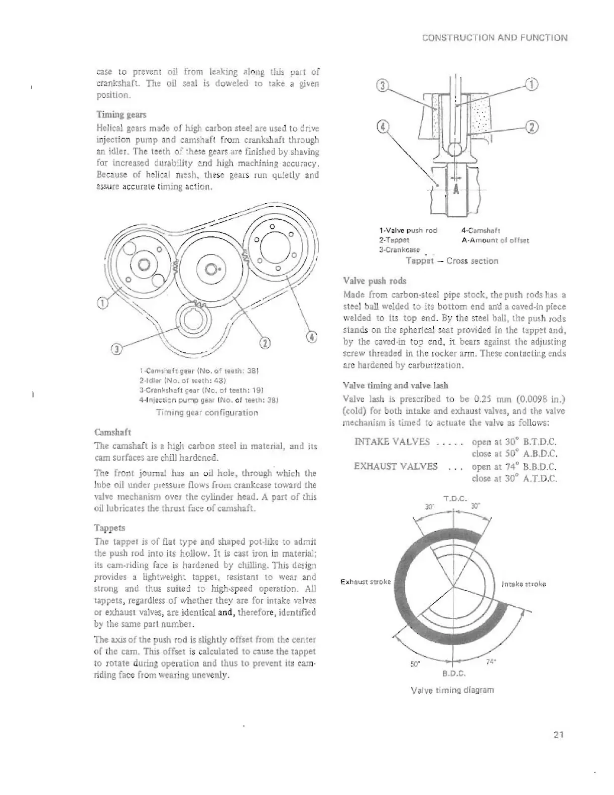
Valv.
timing and valve
Ia<h
Valvo
laID
IS pre,cribed to be 0 .
25
mm (O,0()98 In.)
(cold)
fOI
both Inlake
.nd
exh.
u,
t vah'
es
, and Ihe valve
mechanism
is
timed
[0
actuate the
valve
as
follows:
INTAKE
VA
L
SES
open
at
30'
B,T,D,C,
close
al
SO
'
A,B
,
D,C
,
EXHAUST VALVES open
at
74'
B.B
.D,C.
close al
30'
A. T
.D,
C,
Ex
n
{juH
s'rrok~
T.D.C
.
30'
lY
:::--;--....
B,O.C.
w
Valve timing diagram
Intake
:rlro,ke
21
 Loading...


