Inspection nnd
adju.tment
of
engine
proper
Valve c1eamnee adjuslIMnl
The
valve
clearance specification for
this
engine is 0.
25
mm
(0.0098 In.) for
bo
Ut
inlake
end
exhaust
valves.
This
value
a
ssumes
that
the
engine
is
at
norma
l
tempera
·
ture,
th~re
being no temp
er
ature difference throughout
the bndy
of
the engine. The <hocking
and
adjusting
procedure
is
as
follows
:
(I)
Ro
tat.
the c
rnnk.h.ft
sl
OWl
y
10
bring
the
piston in
No.
I cylinder to
To
p D
e.d
Cenler (TD
C).
This
c
an
be
accomplished
by
observing rocker 3T
mS
of
No
.4
cylinde
r.
As
you turn the crankshaft,
exha
u
st-v
a
lve
ro
ck
er
arm
of
thi
s cylinder
ri
se
s: S
lOp
tu
rnin
g the c
rank
sh
aft
j
ust
when
intake·valve
r
oc
ker
ann be
gi
ns
to go down
af
ter exhaust val
...
e rocker
arm
has oome up
aU
Iho
way
.
Undel
this condi·
tion
,
adju
st
valve
clearance
in
t
he
u
sual
manner
on
intake
and
exhaust
va
l
ves
of
No. 1 cylinder,
intake
valve
of
No. 2 cylmder,
and
,xh.USI
va
l
ve
of
No. 3 cylindeI.
(2) Turn the crmkshaft
on.
complete
rotation
(360' ),
and hold it
th.re
. Adjust the cl
ea
rance on intake
and exhaust valves
of
No.4
cylinder,
exhaust
valve
of
No
. 2 cylinder, and intake valve
of
No.3
cylin·
der.
Adjusting valve clearance
Fan
bell teslon adjustment
Give
a Ihumb pl.ssure to the middle section
of
the be
ll
becwe.n alternator puOey and waler
pump
pulley, and
s
••
how
much t
hi
s pOltion of the belt
den.ct
s by
measuring with a rule.
The
denection
should
be
12
mm
(J
/2
in.): if
nOI
, loosen the mounting bolts
of
the
altematoi holder to displace the
ho
lder
in
order
LO
.Igbten or slacken Ih. bell. Afler obtaining
the
prescribed
amount
of
deflection,
be
:sure
to tighten the bolts good
and hard .
MAINTENANCE
AND
ADJUSTMENT
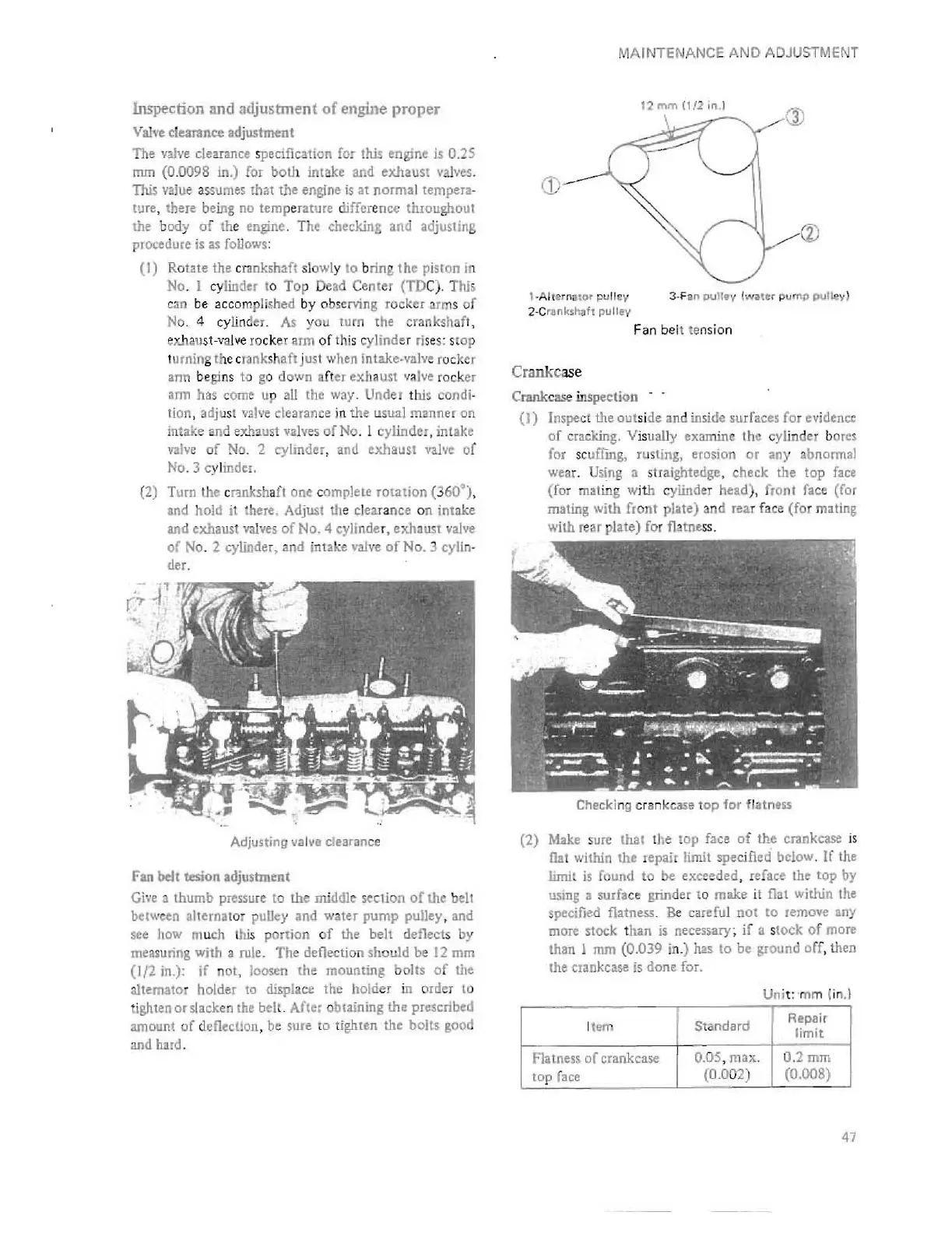
12
mm
(1/2 in.J
(1)
CD
®
, ·Alt
e-
rn
atOl'
pull
ey
3·Fen pulley !water pump P\jlley)
2-C
r!nks~h
pullev
Fan
be
lt te
ns
ion
Cra
nk
c
ase
Crank
case
in
spection
(1)
(llSpe
ct
the
out
si
de
.an
d
inside
surfaces for
evidence
of
cr:u:king. V
is
ually examine Ihe cylindel bores
for
SCUifU1K,
ru
sting, erosion or
any
abnonnal
wear. Using a straightedge, check the
top
fac.
(for mating wi
th
cylinder head), front face (for
mallng with front plale) and
lea
r face (fol mating
with
rear
plate) for flatness.
Checking crank
case
top
for
flatness
(2) Make sure thai the top face
of
the crankcase
is
Oat
within the repair limit spe
ci
fied below.
If
the
limit
is
found
to
be
exceeded,
refac.
Ihe
top
by
usmg
3
surfac
e
grinder
to
make
it
flat
within
the
spe
c
ified
flatness. Be cartful not to
remove
any
more
stock
t
han
is
necess.ary
~
if
3 s
tock
of
more
than 1 mm (0.039 in.) has
to
be
ground
off
, then
the
crankcase
is
done
for.
Uni
t: "
mm
(in
. 1
Item
Standard
Repai r
limit
Flatness
of
crankcase
0.05,
max
.
0.2mm
top
face
(0.002) (0.008)
47
 Loading...


