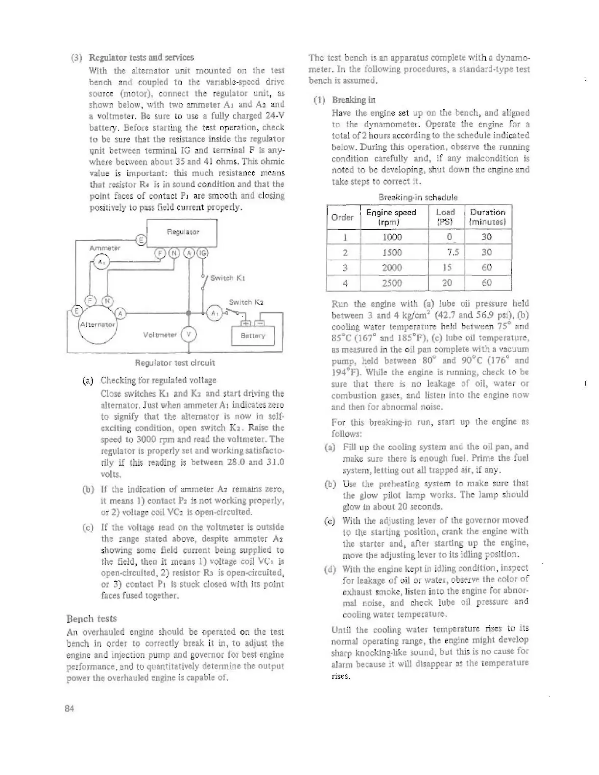
(3) Regulator tests and "'Mee:s
With the alternator unit
mounted
on
the
tes:t
bench
and
coupled to
Ihe
vari'ble-speed drive
source
(molor).
connect the regulator
unit
, as
:shown below·,
with
two
arruneter AJ and A
:i
and
• vohmeler. Be sure
10
use
a fully charged 24-V
battery
. Before starling
the
test o
pe
ration, check
to be su
re
thai the
re
si
stance inside the regulator
ijIlit between terminal
IG
and terminal F is
any
-
where
be
t
ween
about 35 and
41
o
hm
s.
This
ohmic
value is
important
: this
much
resista
nc
e means
that
resistor
R"
is in sound c
on
dition
and
that
the
point
faces
of
con
ta
ct Pl are smoo
th
and closing.
po
si
tively
to
pass.
fie
ld cu
rro
nt
properly
.
RE-Qula
t
or
E
Ammeter
A,
Switch Kl
" • I (
Voltmu.t
r
11
Regu
I ate r
le'St
ci
rcuit
(a) Checking for
regula
led
vo
lt
.ge
Close
switches K. and K, and
,tart
driving the
IIllenlalOr.
Just when ammeter A. indicatestero
to
,ignify that the alternator
is
nOw
in
,eJ[-
t:xclting condition. optn swjtch
K4.
Raise the
spe<:d
10
3000 rpm and read the
vohmeter.
The
regut
..
or
is
properly
"t
and
working
saliEf.cto·
riJy
if
this reading
is
between
28.0 and 31.0
VOllS.
(b)
If the indication
of
ammeter
A>
remains
z.
r
o,
1t
means
1)
t:ont.act
P2
is not working properly,
or
2)
volt,se
coil
YC,
i,
open-drcuited
.
(c) If Ihe
voltage
read on the voltmeter
i,
outside
the
range
stated above.
despHe
ammet-er
A2
showing
!Orne
field
currenl being supplied to
the
field
, then It means 1) "oltage coil VC, is
open.circuited, 2)
resistor
Rl
is open-circuited,
Or
3) conlact P,
is
stuck closed wilh ils point
faces fused logether.
Bench tests
An
overhauled e.
ngine
,hould
be
o
perated
on Ihe t
es
t
bench in order to
correc~y
break it
in
, to
.djust
lhe
engine
and
injectIOn
pump
3Jld
governor
fO!
besl engine
performance, and
to
quantitatively determine the output
power the overhauled
engine
is
capable of.
84
The
ten
bench
is
an appil.r3tus complete
wit
h a
dynamo-
meter.
In
the foliowinE, procedures. 8
standard·
type
test
bench
is
."umed
.
(I)
Breaking in
Ha
ve
the
engine set
up
011
the
bench, and aligned
to the
dynamomete
r. Operate
the
engine for a
total
of2
ho
ur::
acc
ording
to
the
schedule indic
i3ted
below. During this
opera
t
ion,
observe the
running
c-ondition
carefully and I
jf
any malcondition
is
noted
to
be
developi
ng,
shut
down
ti
le engine
and
take
steps
to
correct
it.
Breaking·in
s.c
hedule
,-
E·
d
Load
D
uratio
n
o d I ngme spee
r
er
(rp
m)
IPS)
(m
in
utes)
I
I
10
00
0 30
-
2 1
500
7
.5
30
3
2000
IS
60
4
2500
20
60
- -
----
Run
the engine with
(a)
l
ube
ail
pressure held
between 3
and
4 kg/em' (42.7 and 56.9 p,i), (b)
cooling
water
temperature
held
betwee
n
75
0
and
85'C
(167'
3lld
ISS'F),
(e) lube
oU
lem!X''''tpre,
as
measured
in
the oU pan complete with
i1
vacuum
pump, held between
80'
and 9O'C
(176'
and
194'F).
While
lhe engine
is
running, check
10
be
sure
that
there
is no leakage
of
oil. wate.r
or
combustion
gases.,
and
Iisltn into (he engine
now
and
then
for
abnormal noise.
For
this.
breaking·in run, start
up
the engine
as
fonows:
(a)
FiU
up the cooling system
and
the
oil
P31l,
and
make
,ure there
Is
enough
fuel
. Prime the fuel
system, lelling
ou'
all lIapped air,
if
any.
(b)
U
se
the preheating system
to
make
SUIt::
that
Ihe glow pilot lamp works. The lamp should
glow in
about
20
seconds,
(c) With
the
Adjusting
lever
of
the
governor moved
to
the
.1.riing pOSition , crank the engine with
Ih.
starter and , after slarting up the engine,
move Ihe
ad
justing lever
to
its idling posilion_
(d)
With
Ih.
engine kepI in idling condition, inspect
for
leakage
of
o
il
or wale{, ob,erv. the color
of
exhaust
s.
mok
e,
lis
ten i
nto
the
engine for
abnor·
mal
noise, and check lube
oil
pressu,. and
cooling
water
temperature.
Until the
C()oHng
wa
t
er
temperature-
ri
ses
to its
normal
operating
r"'go,
.
he
e
ogine
might develop
sharp knocking.like
sound,
but
this
is
no c.use for
alarm
because it
will
disappear
as
the temperature
rises.
 Loading...


