Chapter Two: Installation Interface Cables
21
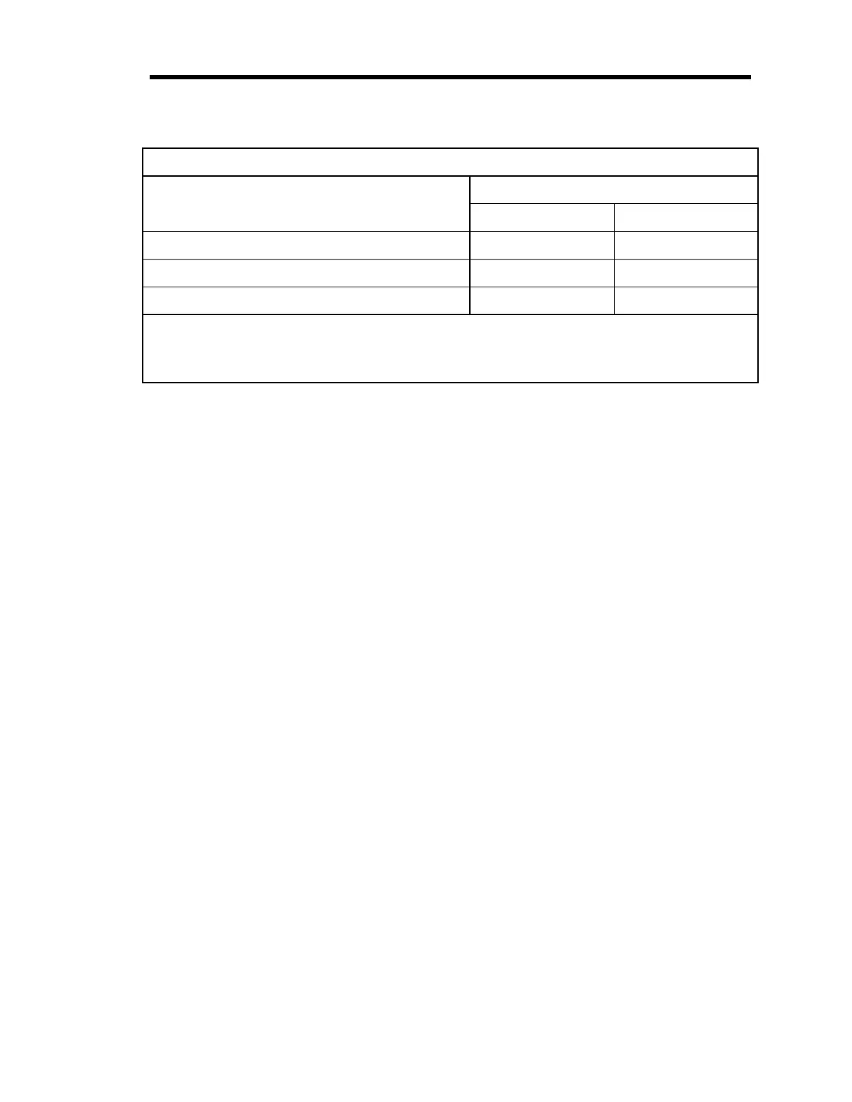
System Interface Cables
(Continued)
To Connect the 246 Unit To... Use the MKS Cable...
Standard Shielded
250 Controller (PCS) CB246-2-3 CB246S-2-3
1250 Controller (PCS) --- CB246-3-3
246 Readout --- CB396-1-2
* To connect the 246 unit to a 1150, 1151, or 1152 MFC, cable CB260S-3-10 or CB260S-3-10
is also required along with the 260 PS-1 or 260 PS-3 Power Supply.
**Products shipped with Edge Card connectors are not CE compliant.
Table 5: System Interface Cables
Generic Shielded Cables
MKS offers a full line of cables for all MKS equipment. Should you choose to manufacture your
own cables, follow the guidelines listed below:
1. The cable must have an overall metal
braided
shield, covering all wires. Neither aluminum
foil nor spiral shielding will be as effective; using either may nullify regulatory compliance.
2. The connectors must have a metal case which has direct contact to the cable’s shield on the
whole circumference of the cable. The inductance of a flying lead or wire from the shield to
the connector will seriously degrade the shield’s effectiveness. The shield should be
grounded to the connector before its internal wires exit.
3. With very few exceptions, the connector(s) must make good contact to the device’s case
(ground). “Good contact” is about 0.01 ohms; and the ground should surround all wires.
Contact to ground at just one point may not suffice.
4. For shielded cables with flying leads at one or both ends; it is important at each such end, to
ground the shield
before
the wires exit. Make this ground with absolute minimum length.
(A ¼ inch piece of #22 wire may be undesirably long since it has approximately 5 nH of
inductance, equivalent to 31 ohms at 1000 MHz). After picking up the braid’s ground, keep
wires and braid flat against the case. With very few exceptions, grounded metal covers are
not required over terminal strips. If one is required, it will be stated in the Declaration of
Conformity or in the instruction manual.
5. In selecting the appropriate type and wire size for cables, consider:
A. The voltage ratings;
B. The cumulative I
2
R heating of all the conductors (keep them safely cool);
C. The IR drop of the conductors, so that adequate power or signal voltage gets to the
device;
D. The capacitance and inductance of cables which are handling fast signals, (such as data
lines or stepper motor drive cables); and
E. That some cables may need internal shielding from specific wires to others; please see
the instruction manual for details regarding this matter.