Chapter Four: Operation How To Setu
the S
stem
53
Chapter Four: Operation
How To Setup the System
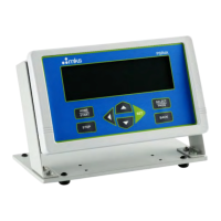
1. Verify that the LINE VOLTAGE SELECTOR switch on the underside of the 246 unit is
set to the proper input voltage, and ensure that the fuse type is appropriate for your
voltage setting.
Refer to Table 6, page 31, and
Line Voltage
, page 32, for more information.
Caution
The Line Voltage Selector Switch must be set to the proper input
voltage
before
you connect the AC line cord. Otherwise, the unit will
be severely damaged.
2.
Before
connecting
any cables or a mass flow controller to the 246 unit, apply power to
the unit by connecting the AC LINE CORD and check that the DIGITAL PANEL
METER on the 246 unit reads 000, ±1 count.
For protective earthing, plug the power cord into a properly grounded outlet.
Caution
The 246 unit uses the AC line cord as its power switch, that is, the
unit is
ALWAYS ON
when connected to a line source.
If the DPM does not read 000, adjust the ZERO CONTROL on the front panel of the 246
unit until it does. Note that the zero control potentiometer is sensitive when no MFC is
attached to the unit.
3. Disconnect the AC LINE CORD to turn off power to the unit.
4. Set the front panel controls on the 246 unit as listed in Table 10.
Type 246 Unit Setup - Front Panel Controls
Control Switch Position
Flow Control Switch OFF
Set Point Source Switch FLOW
Table 10: Type 246 Unit Setup - Front Panel Controls