Chapter Three: Overview Front Panel Controls
39
Front Panel Controls
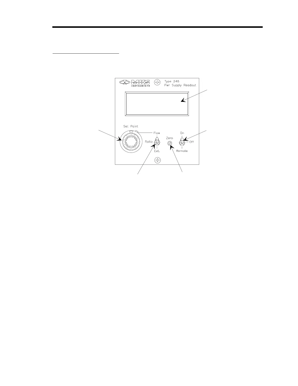
Figure 7 shows the location of the controls on the front panel of the 246 unit.
Window
1
0
1
0
3
0
20
40
50
60
70
80
90
Di
ital Panel
Meter
Flow Control
Switch
Zero Control
Set Point Source
Switch
Set Point
Control
Figure 7: Front Panel Controls
Digital Panel Meter
This 3½ digit panel meter (DPM), set to read 1 VDC as 1000 counts full scale, displays the flow
rate. In order for the meter to display a
direct
flow reading, in sccm or slm, the Gauge Factor
Scaling Control potentiometer on the rear panel (refer to Figure 8, page 41) must be properly set.
Refer to
Gauge Factor Scaling Control
, page 44, for more information.
Flow Control Switch
This 3-position toggle switch controls the circuit which applies the set point signal to the MFC as
follows:
ON: Allows flow control via the 246 set point voltage.
OFF: Shuts off flow (overrides the 246 unit’s set point voltage). The switch places a
small negative voltage on the set output line so that the control valve will be
closed positively.
REMOTE: Provides for external command of ON/OFF flow control.
A logic signal coming in through Interface connector J9 (pin 4) may be used to
gate the set point signal to the MFC. Flow may be turned ON/OFF by an
external TTL signal; a logic low turns the flow ON, a logic high or open turns
the flow OFF. Refer to Table 7, page 33, for the Interface connector J9 pinout.