Chapter Three: Overview Rear Panel Controls
41
Rear Panel Controls
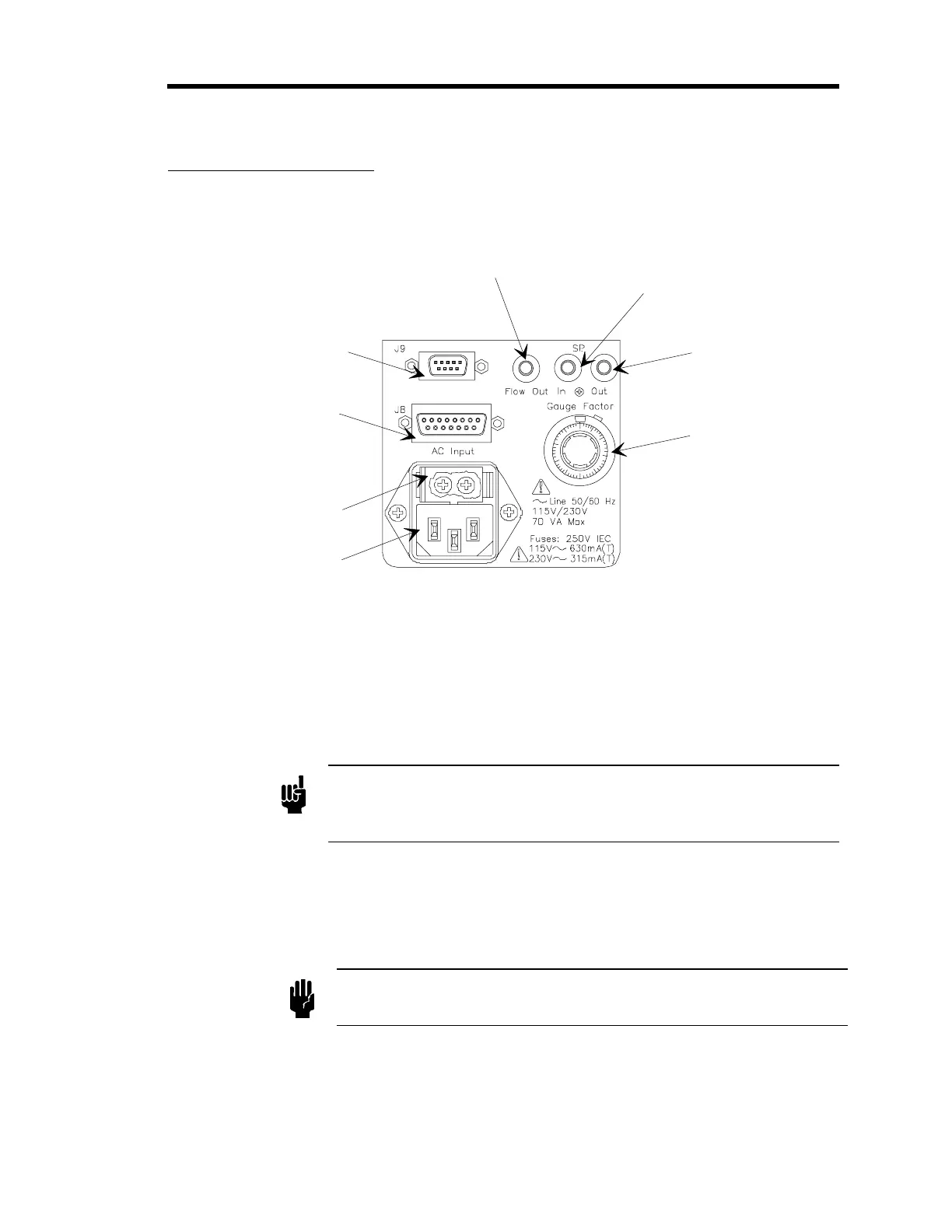
Figure 8 shows the location of the controls on the rear panel of the 246 unit.
Window
1
0
1
0
3
0
20
40
50
60
70
80
90
Set Point In
Micro
ack Connector
Set Point Out
Micro
ack Connector
Gau
e Factor
Scalin
Control
Flow Out Micro
ack
Connector
9-Pin Male T
pe "D"
Interface Connector J9
15-Pin Female T
pe "D"
MFC Connector J8
Fuse Holder
AC Line Cord
Connector
Figure 8: Rear Panel Controls
Gauge Factor Scaling Control Potentiometer
This 10-turn potentiometer is used to enter the scaling factor, which scales down the +5 VDC
transducer output signal so that the Digital Panel Meter displays the flow rate directly in sccm or
slm. Normally set to “1/00”, it can be raised or lowered for use with a particular gas.
Note
It is
critical
for proper system operation that the scaling control factor is
calculated properly and that the potentiometer is set correctly. Refer to
Gauge Factor Scaling Control,
page 44, for more information.
AC Line Cord Connector
The AC Line Cord provides 115 or 230 VAC power to the 246 unit. For protective earthing,
plug the power cord into a properly grounded outlet.
Caution
The 246 unit uses the AC line cord as its power switch, that is, the
unit is
ALWAYS ON
when connected to a line source.