Gauge Factor Scaling Control Cha
ter Three: Overview
46
Scaling Control Potentiometer
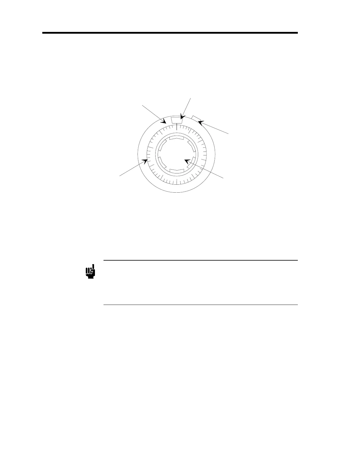
The Scaling Control (refer to Figure 9) is a 10-turn potentiometer that serves as a voltage divider
for the +5 VDC output signal from the MFC; the control has a full scale setting of 1000.
Window
Outer Control
(Sets factors of 100)
Inner Dial
(Sets factors of 10)
Window
Slide Lock
Adjustment Knob
10
20
30
40
50
60
70
80
90
0
1
Figure 9: Scaling Control Potentiometer - Initial Setting
The outer control represents factors of 100; indicated by the numbers 0 to 10 which display in the
window at the top of the potentiometer. The numbers on the inner dial represent factors of 10, in
divisions of 2; these values are set when the appropriate value is aligned with the vertical line
beneath the window. The adjustment knob cannot be turned below 0 or above the full scale
setting of 1000.
Note
The maximum number of counts the meter can read is 1999, therefore the
voltage cannot exceed 2 VDC. Ensure that the scaling control
potentiometer is never set higher than “2/00”, that is a “2” in the window
and “0” on the dial. This ensures that the voltage is never set higher than
2 VDC, and that the meter is not be set beyond its capacity.
To adjust the Scaling Control Potentiometer:
•
Unlock the slide lock on the right side of the control by pushing it up (counterclockwise)
•
Turn the adjustment knob
clockwise
to increase the value represented on the control
The 246 unit is typically shipped with the control set to “1 / 00”, as shown in Figure 9.
•
Turn the adjustment knob
counterclockwise
to decrease the value represented on the
control
•
Lock the position of the control by pushing the slide lock on the right side of the control
down (clockwise)
Refer to
How To Setup the System
, step 7, page 56, for an example of how to adjust the Scaling
Control potentiometer.