Chapter Two: Installation S
stem Confi
urations
27
CB396S-1-2
"Master" 246 Unit
(Channel 1)
"Slave" 246 Unit
(Channel 2)
"Slave" 246 Unit
(Channel 3)
CB396S-1-2
Window
1
0
10
30
20
40
50
60
7
0
8
0
90
Window
1
0
10
30
20
40
50
60
7
0
8
0
90
Window
1
0
10
30
20
40
50
60
7
0
8
0
90
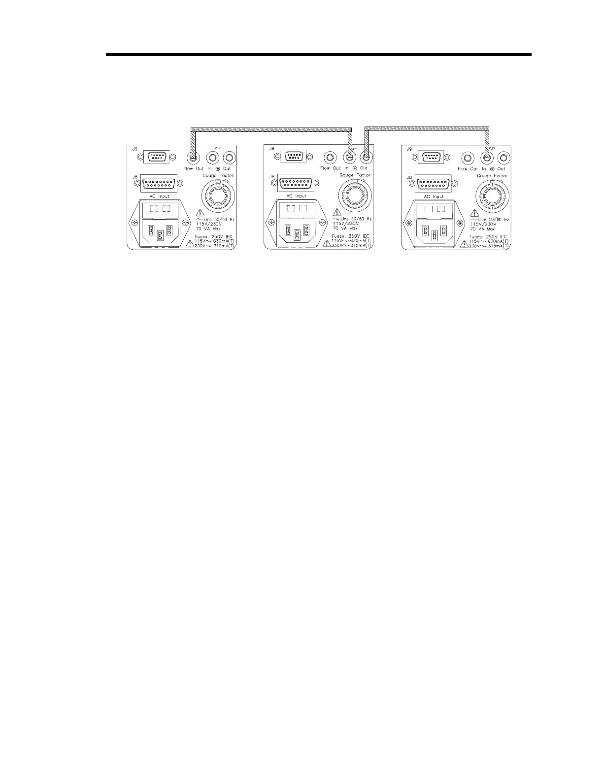
Figure 4: Internal Set Point Control Setup - Ratio Flow Control
The flow rate for the first unit in the string (the
“master”
) is controlled with its front panel SET
POINT CONTROL, which is connected to an internal +5 V reference. Since the +5 V
corresponds to full rated flow, the master’s SET POINT CONTROL can be adjusted up to a
maximum of 100% of the rated flow for the attached MFC. The flow rates for each of the
“slave”
246 units are set using their front panel SET POINT CONTROLS, as a fraction (ratio) of
the output flow from the master 246 unit. The ratio is maintained while the total flow is adjusted
to maintain the desired pressure. Refer to
How To Manually Control Ratioed Gas Flows
, page
61, for operating instructions.