Chapter Two: Installation Connectors
33
Connectors
The 246 unit’s two interface connectors and three microjack connectors are located on the rear
panel of the unit (refer to Figure 8, page 41). The system interface cables are listed in Table 5,
page 20.
Interface Connector J9
This 9-pin male Type “D” connector provides the communication link to and from the unit
including the connection to the scaled transducer outputs, the lines to turn the flow on and off,
and the set point input lines which remotely set the flow rate of the MFC.
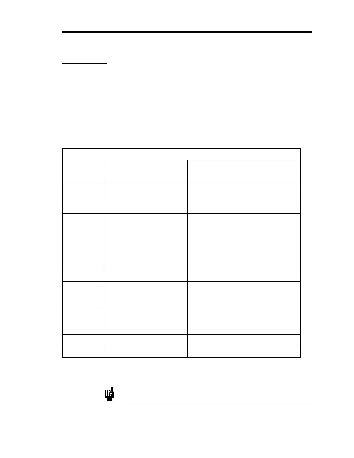
Interface Connector J9 Pinout
Pin Assignment Description
1 Analog Return
2 0 to 1 V (nominal)
Corrected Output
Flow output corrected by rear panel
Gauge Factor Scaling Control
3 Analog Return
4 Remote ON/OFF Line used for an external (remote) control
of flow controller. Compatible with all 5
V logic, this line is held high (or left
unconnected), causing a flow “off”
condition when the SET POINT
SOURCE SWITCH is in the EXT
position.
5 No Connection
6 0 to 5 V Output MFC output voltage, after being zero
corrected by the front panel ZERO
CONTROL circuitry
7 Set Point Input Line used to input an external set point
signal for direct control (EXT position)
or ratio control (RATIO position)
8 Digital Ground Return for remote ON/OFF line (pin 4)
9 Chassis Common
Table 7: Interface Connector J9 Pinout
Note
The “No Connection” pin assignment refers to a pin with no internal
connection.