How To Setup the System Cha
ter Four: O
eration
56
7. Adjust the GAUGE FACTOR SCALING CONTROL potentiometer for each MFC in
use.
The Scaling Control potentiometer sets the value of the Scaling Control Factor.
Note
It is
critical
for proper system operation that the Scaling Control
Potentiometer is set correctly. Refer to
Gauge Factor Scaling Control,
page 44
,
for more information.
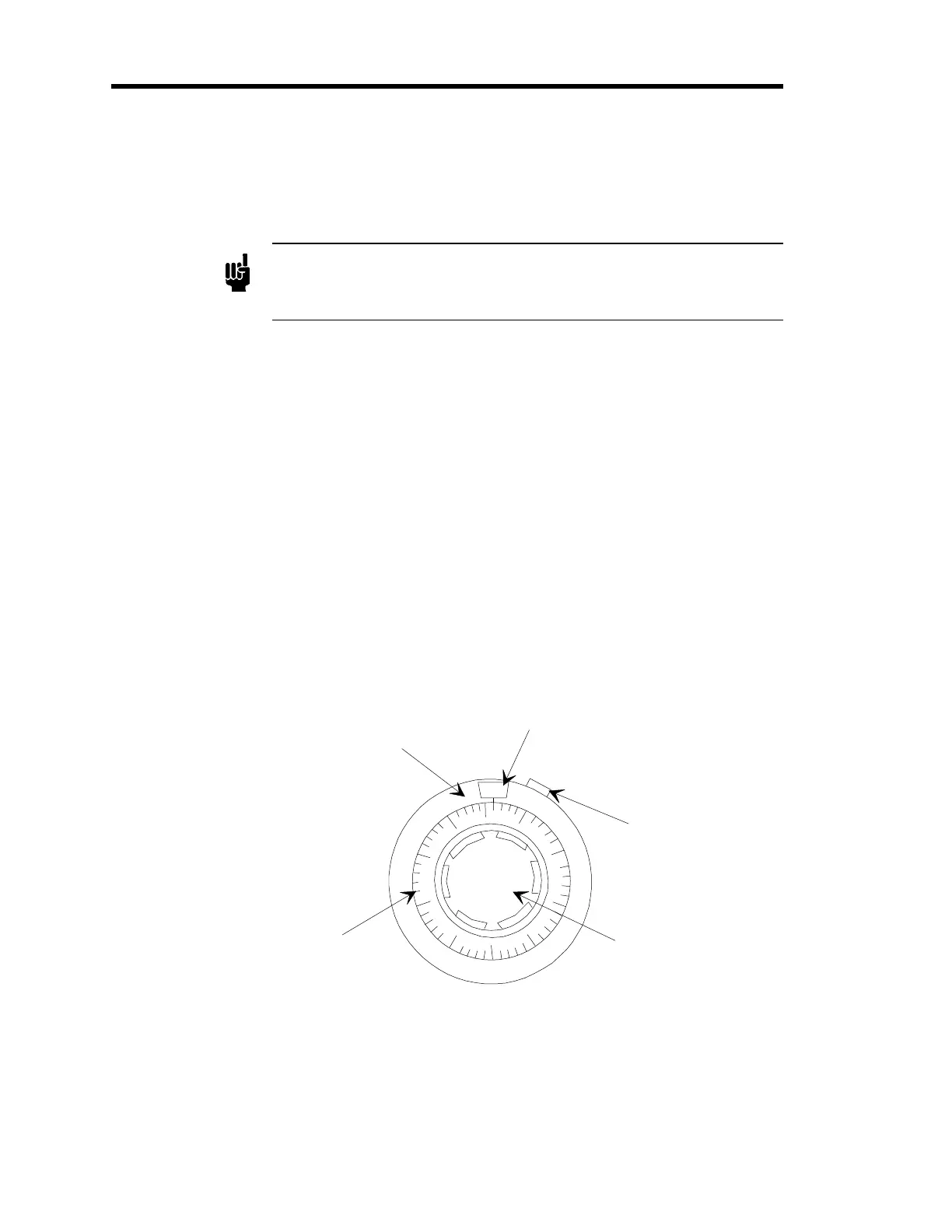
The outer control represents factors of 100; indicated by the numbers 0 to 10 which
display in the window at the top of the potentiometer. The inner dial represents factors
of 10, in divisions of 2; these values are set when the appropriate value is aligned with
the vertical line beneath the window. The adjustment knob cannot be turned below 0 or
above the full scale setting of 1000.
To adjust the Scaling Control Potentiometer to the setting of “278” calculated in the
example in step 6, page 54:
a. Unlock the slide lock on the right side of the control by pushing it up
(counterclockwise).
b. Turn the adjustment knob clockwise until the “2” appears in the window.
c. Continue turning the adjustment knob until the line on the dial which represents
“78” is aligned with the vertical line beneath the window, as shown in Figure 11.
d. Lock the position of the control by pushing the slide lock on the right side of the
control down (clockwise).
Outer Control
(Sets factors of 100)
Inner Dial
(Sets factors of 10)
Window
Slide Lock
Adjustment Knob
0
90
2
70
60
50
40
30
20
10
80
Figure 11: Gauge Factor Scaling Control Potentiometer - Example Setting
(Set to “2/78”)