Maintenance Cha
ter Five: Maintenance and Troubleshootin
68
3. Disconnect all cables from the connectors located on the rear panel of the unit.
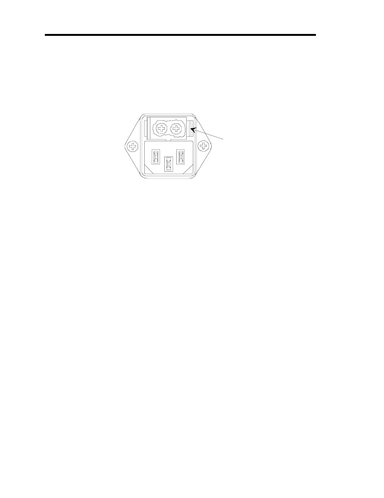
4. Insert a small device, such as a flat head screwdriver in the fuse holder clip on the right
side of the fuse holder.
Refer to Figure 12 for the location of the fuse holder clip.
Fuse Holder
Clip
Figure 12: Fuse Holder Clip
5. Gerntly press against the clip and push up with the screwdriver until the plastic fuse
holder pops out.
It may be necessary to repeat steps 4 and 5 on the left side in order to get the fuse holder
to release.
6. Remove the existing fuses.
7. Place the new fuses into the unit.
8. Gently snap the fuse holder back into place.
9. Connect any cables removed from the back of the 246 instrument in step 3.
10. Connect the power cord.