Chapter Two: Installation S
stem Confi
urations
29
Ratio Flow Control
For ratio flow control, the system requires two or more 246 units connected together, the MFCs,
an external pressure controller, a pressure transducer, and the appropriate cables.
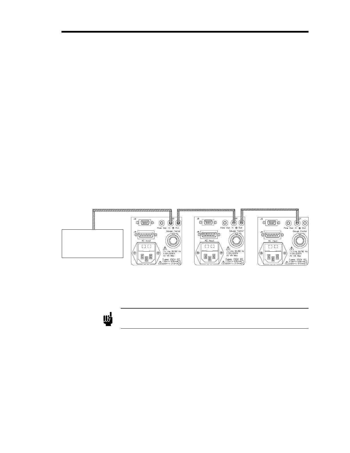
To connect multiple 246 units together with an external controller (refer to Figure 6):
1. Connect the proper interface cable from the external controller to the SP IN jack on the
first slave 246 unit.
2. Connect the SP OUT jack on the first slave 246 unit to the SP IN (Set Point In) jack on
the second slave 246 unit.
3. Connect the second slave (Channel 2) 246 unit’s SP OUT (Set Point Out) jack to the
next 246 unit’s SP IN jack (Channel 3).
The Set Point In and Set Point Out jacks are internally connected in parallel.
4. Continue to join the 246 slave units together by connecting the SP OUT jack on one unit
to the next 246 unit’s SP IN jack until all of the units are connected.
CB396S-1-2
"Slave" 246 Unit
(Channel 2)
"Slave" 246 Unit
(Channel 3)
"Slave" 246 Unit
(Channel 4)
CB396S-1-2
Window
1
0
1
0
30
20
40
50
60
7
0
8
0
90
Window
1
0
1
0
30
20
40
50
60
7
0
8
0
90
Window
1
0
1
0
30
20
40
50
60
7
0
8
0
90
CB246S-2-3
T
pe 250 Controller
(External Set Point Volta
e)
External "Master"
(Channel 1)
Figure 6: External Set Point Control Setup - Ratio Flow Control
Note
The drawing in Figure 6 is not drawn to scale.
The pressure in a chamber is maintained by controlling the ratio of gas flows, based on the set
point signal from an external controller and measurements from a pressure transducer.
The controller (the “
master”
) provides a pressure control signal (PCS) that is applied to the SET
POINT CONTROL on the first slave 246 unit. The external set point voltage bypasses the first
slave 246 unit’s SET POINT CONTROL and the flow signal is sent directly to the MFC. The
flow rates for the remaining slave 246 units are set using their front panel SET POINT
CONTROL, as a fraction (ratio) of the output from the first slave 246 unit. The ratio is
maintained while the total flow is adjusted to maintain the desired pressure. Refer to
How To
Control Ratioed Gas Flows with an External Set Point
, page 63 for operating instructions.