e-Vision and e-Vision+ LP101013.100 – 01 January 2004
MKS Instruments, Spectra Products
14
3. Connections
3.1 The rear panel
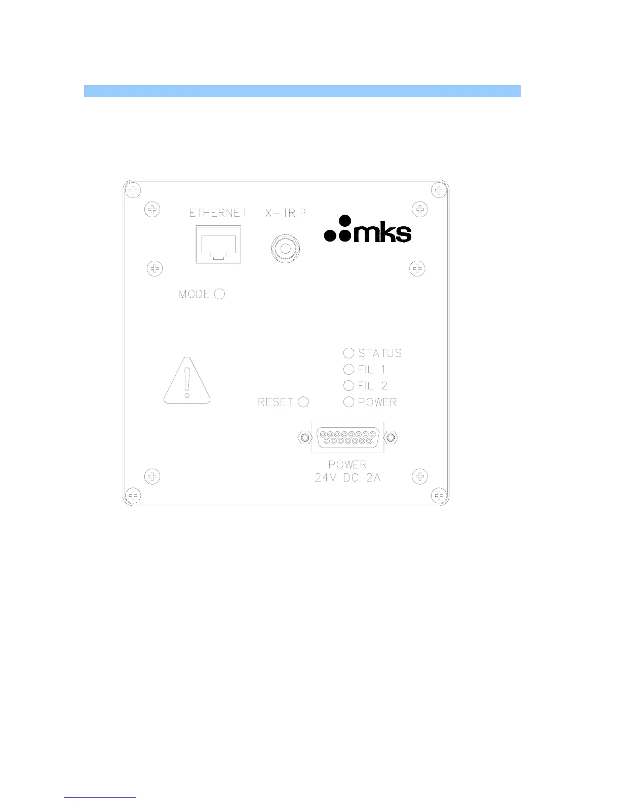
Please refer to Figure 1 for the arrangement of the connectors on the rear panel.
Pin numbers are marked on the various connectors.
Figure 1. Rear panel arrangement
3.2 Power connector
This 15-way D-Type socket labeled “POWER” on the rear panel of the unit is used
to connect the low voltage power supply unit.
The pin connections are as follows:
1, 2, 3 (joined together) +24 volts DC
9,10,11 (joined together) 0 volts (24 volt return)
Connector Shell functional earth
The power input is 24 volts DC ± 10%, 2 Amps max.
The current drawn depends on the mass range and whether a filament is on or off.
The primary power circuit is galvanically isolated from the system ground.