49/112
First Installation Steps
© MOBOTIX AG • Security-Vision-Systems • Made in Germany
www.mobotix.com • sales@mobotix.com
1.
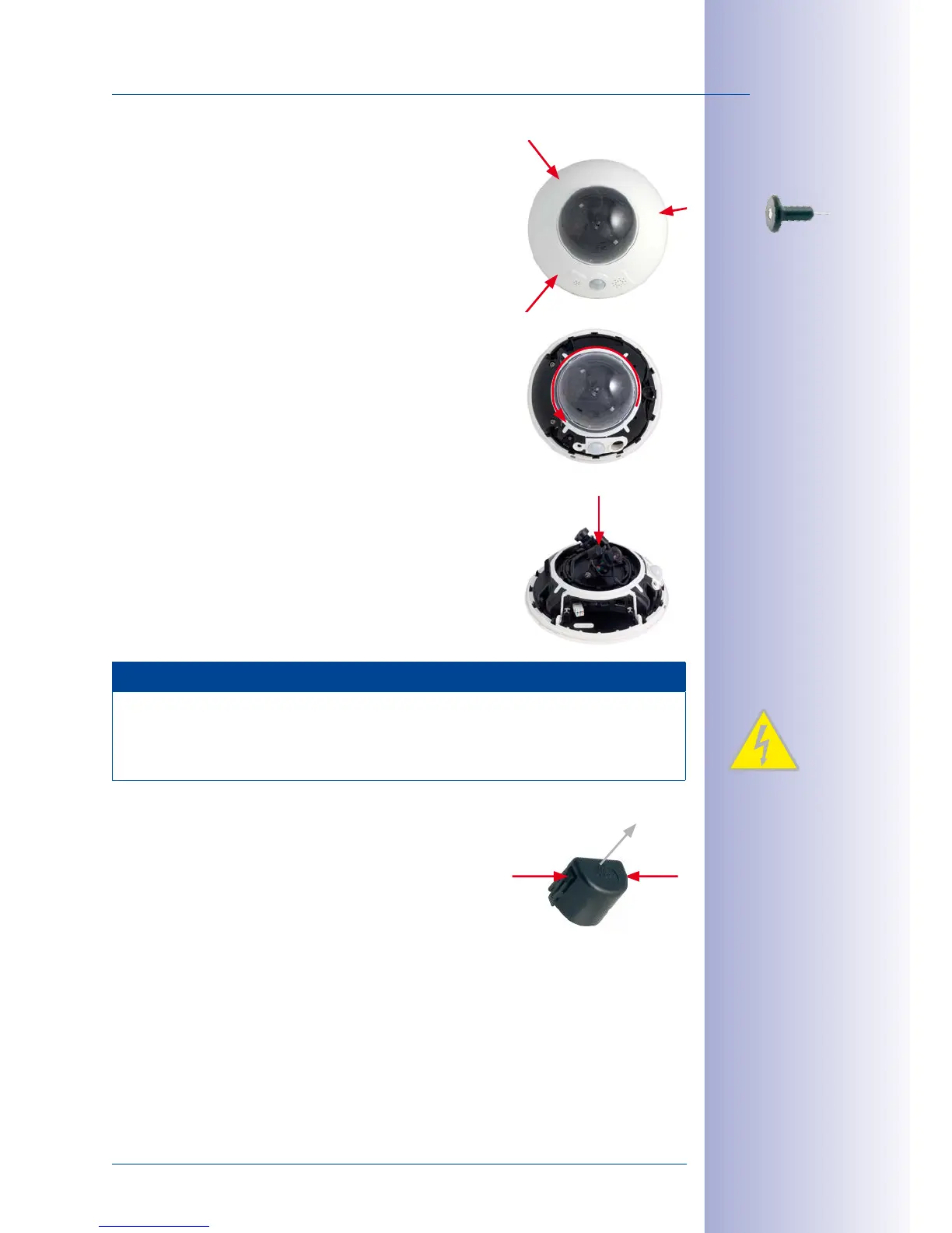
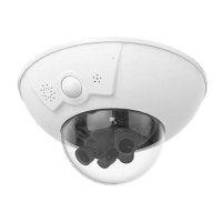
Remove the outer shell
: Remove the outer shell using
the supplied custom tool. Insert the tip of the custom
tool into the three small holes of the shell, one by one.
Lift the outer shell to loosen it from the fixtures.
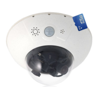
2.
Remove the dome
: Pick up the dome using the sup-
plied plastic foil or a cotton cloth and remove it by
turning it counterclockwise.
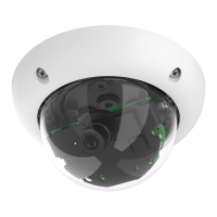
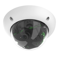
3.
Insert the lens units and mount the central lens
screw
: Remove the center lock screw and the washer.
Insert the lens units into the seatings. Insert the lock
screw with a washer into the center of the camera
and gently tighten it to hold the lens units in place.
Note
Touch the mount of the lens units only. Always avoid direct contact with the contacts
on the green circuit board (ESD) in order to prevent damage arising now or later and
to avoid reducing the service life.
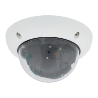
4.
Remove the lens cover on the image sensors
: Press
the two bars on the side of each lens cover (red
arrow) and remove the covers one after another in
the direction of the gray arrow.
Use the supplied
custom tool
Max. tightening
torque of the lock
screw: 1 to 1.2 Nm