Layout of the XC100
03/05 AWB2724-1453GB
8
Assembly
The voltage connection 0V
Q
/24V
Q
is only for the supply voltage to
the integral local inputs (8) and outputs (6), and is electrically
isolated from the bus.
The 0V/24V voltage connection is internally filtered and buffered
and fed to a voltage transformer which generates the required
system voltages. The internal power supply for the 5 V system
voltage is designed so that the processor unit is supplied with the
required current.
Table 1: Limitations which apply when using the XC100-CPU and the
XIOC-Signal modules in an ABS plastic enclosure
If there is an interruption break or collapse of the 24 V supply
(threshold is about 10 V) then a power-down logic switches of the
5 V supply to the signal modules (central I/O). The sequence is
initiated by the PFI signal and leads to a power-down through the
CPU.
Local digital inputs
The 18-pole terminal block which has the power supply to the
CPU, the local I/Os and the physical connection to the local
inputs/outputs is located on the right half of the CPU behind the
front enclosure.
The eight digital inputs and six semiconductor outputs are
designed for 24 V signals and have a common 0VQ/24VQ power
supply which is potentially isolated right up to the bus.
The outputs Q0.0 to Q0.5 can be loaded with 500 mA, a duty
factor (ED) of 100% and a utilization factor (g) of “1”.
The outputs are short-circuit proof. A short-circuit state should,
however, not be permitted to exist over a longer period.
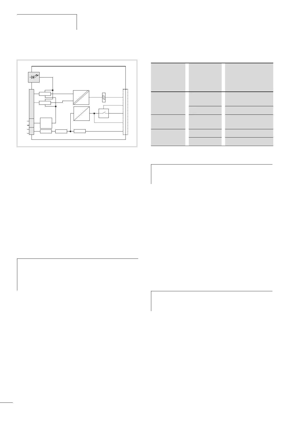
Figure 3: Block diagram: power supply unit
a Status indicator for I/Os
b Front connection terminals
c Internal filter
d Buffer
e XIOC I/O-bus, module rack
PFI = Power Fail Interrupt
i
Caution!
When using the XC100-CPU and the XIOC-Signal
modules in an ABS plastic enclosure, the limitations
stated in table 1 apply. ABS enclosures are identified with
“ABS” on the surface which faces the backplane.
24 V
0 V
24 V
Q
0 V
Q
Enable
VCC I/O
5 V H
8 DI
24 V H
PFI
5 V H
3.3 V H
24 V H
6 DO
a
b
cd
e
Fitted in: Installation
location
internal
temperature:
Current rating of the 5 V
system voltage of the
I/O bus
CI enclosure > 40 °C Use of the XC100 not
permissible
0 to 40 °C max. 1.5 A
1
Distribution
fuse-board
0 to 55 °C max. 1.5 A
1
Control panel > 40 °C max. 1.5 A
1
0 to 40 °C max. 3.2 A
1) On the outputs of the CPU made of ABS enclosure material, a
utilization factor g of 0.5 applies
h
Limitations in performance for the digital I/O modules
with ABS enclosures are described in the documentation
for the XIOC signal modules (AWB2725-1452GB).
h
Important
Please observe the limitations of performance for the
outputs with ABS enclosures in a table 1.
 Loading...

