EasyManua.ls Logo

Moeller XC-CPU101-C64K-8DI-6DO User Manual

Moeller XC-CPU101-C64K-8DI-6DO
82 pages
To Next Page IconTo Next Page
To Previous Page IconTo Previous Page
Page #38 background imageLoading...
Page #38 background image
Program processing and
system time
03/05 AWB2724-1453GB
34
Interrupt processing
In the XC100 it is possible to program and parameterize up to
seven interrupt events. Interrupts can be activated by:
physical inputs I0.0 to I0.3 of the XC-CPU101
XIOC signal modules with interrupt features
TIMER_Interrupt.
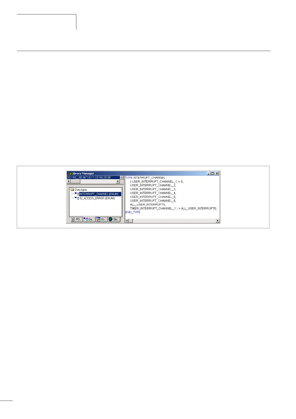
The interrupt events listed in figure 44 are available:
If an interrupt occurs, the runtime module executes the program
organisational unit (POU) which is linked to the interrupt source.
Execution of the POU is time-monitored. The parameterized cycle
time is used for this cycle time. The interrupts are enabled when
changed to the RUN state and inhibited when changed to the
STOP state. Interrupt sources which are not enabled in the
configuration do not initiate an interrupt. If a POU is not assigned
to an enabled interrupt source, the interrupt is recognised and
executed but without running a POU.
Frequent occurrence of an interrupt during a cycle can cause the
cycle time to time-out and result in a reset being initiated by the
Watchdog.
User interrupts can be inhibited and re-enabled from the program.
The “DisableInterrupt” and “EnableInterrupt” functions are
provided for this purpose. A call parameter in the XSoft determines
if an individual interrupt or all interrupts are enabled or inhibited.
Enabling of an inhibited interrupt must be performed with the
same parameter used to inhibit it.
Both the “DisableInterrupt” and “EnableInterrupt” functions are
components of the “XC100_Util.lib” library. This library must – if
not already done so – be integrated into the library manager of the
XSoft.
Figure 44: User events

Table of Contents

Question and Answer IconNeed help?

Do you have a question about the Moeller XC-CPU101-C64K-8DI-6DO and is the answer not in the manual?

Moeller XC-CPU101-C64K-8DI-6DO Specifications

General IconGeneral
ModelXC-CPU101-C64K-8DI-6DO
TypeController
Memory64 KB
Digital Inputs8
Digital Outputs6
CategoryPLC

Summary

Layout of the XC100

CPU with PSU and Local Inputs/Outputs

Describes the CPU module's compact design with processor and 24V PSU.

24 V PSU with Local Inputs/Outputs

Details the power supply unit for processor and I/Os.

Local Bus Expansion with XIOC-BP-EXT

Details backplane expansion capabilities.

CPU Module Overview

Describes the XC-CPU101 processor with integrated CAN interface.

CANopen Interface

Connects CPUs to the CANopen bus via an electrically isolated ISO-11898 interface.

CPU Installation

Provides instructions for installing the CPU module onto the rack.

Detaching the CPU

Provides steps to remove the CPU module.

Engineering

Preventing Interference

Guidelines for reducing electromagnetic interference in cabinets.

Lightning Protection

Measures for external and internal lightning protection.

CPU Operation

Switch-on Behaviour

Describes the CPU's self-test and OS loading after power-on.

Start Behaviour

Explains controller start based on selector switch and parameters.

Test and Commissioning Features

Features for testing and commissioning the PLC.

Breakpoint and Single-Step Mode

Allows setting breakpoints and executing code step-by-step.

Program Reset Options

Explains Warm, Cold, and Full reset options.

Program Parameterization

Details parameters adjustable in the programming system.

Creating and Transferring Boot Project

Guides on generating and saving a boot project on MMC.

Updating the Operating System (OS)

Procedure for updating the PLC's operating system.

Program Processing and System Time

Cycle-Time Monitoring

Monitors application cycle time via hardware timer.

Direct Peripheral Access

Enables direct access to local/central I/O signals.

XC100_SysLibCom.lib Library

Functions for operating the RS232 interface in transparent mode.

XC100_Util.lib Library

Blocks for integrating functionalities like CAN bus load.

Interrupt Processing

Describes how to program and parameterize up to seven interrupt events.

Timer Interrupt

Provides an interrupt channel for timer events.

Creating and Integrating an Interrupt Function

Guides on creating and assigning interrupt functions.

Parameterization of the Interrupt Source

Details setting up interrupt sources in task configuration.

Program Transfer

Describes transferring application programs and creating backups.

Addressing Inputs/Outputs and Marker

Activate Automatic Addresses

Automates address assignment or modification of modules.

Activating Check for Overlapping Addresses

Detects and reports duplicate address assignments.

Free Assignment of I/O and Diagnostic Addresses

Allows manual assignment/modification of I/O and diagnostic addresses.

Run Automatic Calculation of Addresses

Recalculates all addresses based on current configuration.

Diagnostics Functions

Explains running diagnostics using function blocks.

Establishing a PC – XC100 Connection

XSoft Software for Configuration

Use XSoft to define communication parameters.

Communication Parameters Setup

Guides on setting communication parameters in XSoft.

Create Sample Project

Configure the XC100 Controller

Steps to configure the XC100 with local/central I/Os.

RS232 Interface in Transparent Mode (COM 1/2/3)

Demands on Functionality of Transparent Mode

SysComOpen Function

Opens the RS232 interface for transparent mode.

SysComClose Function

Closes any RS232 interface opened in transparent mode.

SysComRead Function

Reads received data via RS232 in transparent mode.

SysComWrite Function

Allows output of data via the RS232 interface.

SysComSetSettings Functions

Sets RS232 interface parameters for transparent mode.

SysComReadControl Function

Reads control/interface lines of COM2/COM3.

SysComWriteControl Function

Writes to control/interface lines of COM2/COM3.

Related product manuals