EasyManua.ls Logo

Moeller XC-CPU101-C64K-8DI-6DO User Manual

Moeller XC-CPU101-C64K-8DI-6DO
82 pages
To Next Page IconTo Next Page
To Previous Page IconTo Previous Page
Page #60 background imageLoading...
Page #60 background image
Programming via CANopen
network (Routing)
03/05 AWB2724-1453G
56
Alternatively, you can use the BlockSizeEditor application to
change the block size.
The download block size is defined in the following Registry key:
[HKEY_LOCAL_MACHINE\SOFTWARE\3S-Smart Software Solutions
GmbH\Gateway Server\Drivers\Standard\Settings\Tcp/Ip (Level 2
Route)]
"Blocksize"=dword:00020000
The default block size is 20000
hex
(=128 Kbyte), the block size for
routing is 1000
hex
(= 4 Kbyte).
Notes
If large files are written to the target PLC or read from the PLC,
it is possible that the online connection will be interrupted after
the transfer process has been completed. Renewed connection
is possible.
If a program with a modified routing node ID is loaded into the
target PLC, the target PLC accepts the modified routing node ID;
however, the communication connection will be interrupted.
Reconnection with a corrected routing node ID is possible.
If a PLC receives a program without valid routing parameters
(baud rate/node ID), this PLC cannot be connected via a routing
connection.
The routing is independent of the configuration (master/slave):
a target PLC that has not been configured as a master or as a
slave can be accessed. It must only receive the basic parameters
such as node ID and baud rate, as well as a simple program.
Addressing
PLCs on the CANopen bus can be configured as a master or as a
device. The PLCs are assigned with a Node ID/node number
(address) in order to uniquely identify them. If you wish to use the
routing function to access a (target) PLC, you must assign the
target PLC with a further (Routing) Node ID.
Procedure
X Connect the PC to a PLC.
X Select the target PLC with which you want to communicate for
the project.
X Determine the communication settings for the PC and the PLC
connected to the PC.
X Enter the target ID (target ID = Node ID!) of the target PLC as
in the example and log on.
You can run the following functions:
Program download
Online modification
Program test (Debugging)
Create bootable project
Filing source code.
Note for project creation:
The node ID/node number and the baud rate of the target PLC to
the routing function can be defined in the Additional parame-
ters tab in the PLC Configuration window:
Enter the baud rate on the CANopen bus and the Node-ID/node
number in the “RS232 l CAN routing settings” field.
This field appears with the XC200, after you have confirmed it in
the Activate field. This activation is necessary to ensure that the
PLC can communicate via the CANopen bus.
Node ID and baud rate are transferred with the project download.
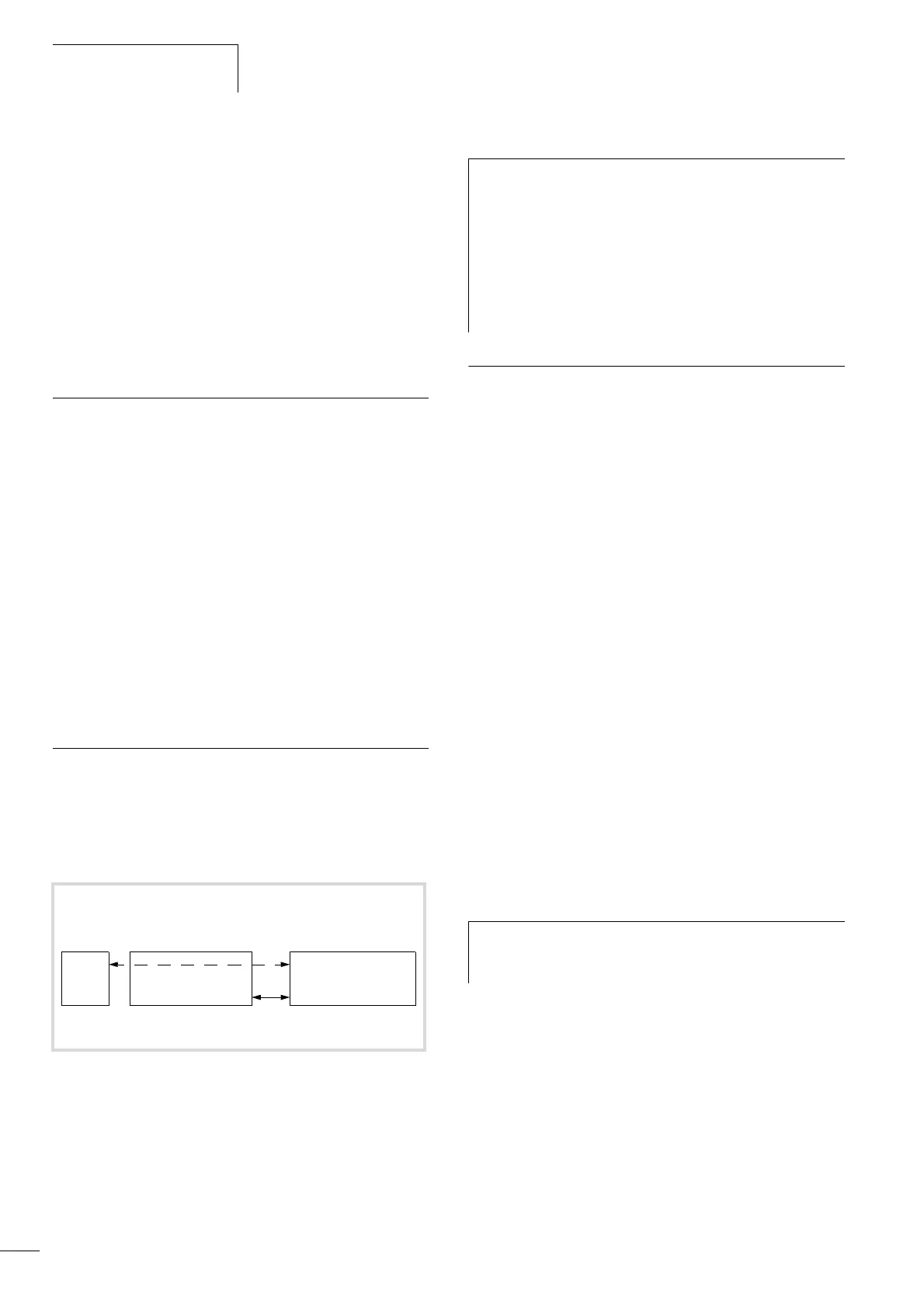
Figure 76: XC100/200, XN-PLC on the CANopen bus, routing principle
PC
Routing PLC XC100/
200/XN-PLC
(master/device)
Node ID 1
Target PLC
XC100/200/XN-PLC
(device)
(Routing) Node ID n
1)
Node ID n
1)
CANopen
h
The following applies for the Node ID of the device func-
tion and the Node ID of the routing function:
XC100 with operating system < V2.0 or XC200:
The routing node ID must be not equal to the device
node ID.
XC100 with operating system f V2.0 or XN-PLC:
The (routing) Node ID must be equal to the Node ID
(device)!
h
In order to guarantee a speedy transfer of data, the
routing with the CANopen should only be performed with
a baud rate of at least 125 Kbit/s.

Table of Contents

Question and Answer IconNeed help?

Do you have a question about the Moeller XC-CPU101-C64K-8DI-6DO and is the answer not in the manual?

Moeller XC-CPU101-C64K-8DI-6DO Specifications

General IconGeneral
ModelXC-CPU101-C64K-8DI-6DO
TypeController
Memory64 KB
Digital Inputs8
Digital Outputs6
CategoryPLC

Summary

Layout of the XC100

CPU with PSU and Local Inputs/Outputs

Describes the CPU module's compact design with processor and 24V PSU.

24 V PSU with Local Inputs/Outputs

Details the power supply unit for processor and I/Os.

Local Bus Expansion with XIOC-BP-EXT

Details backplane expansion capabilities.

CPU Module Overview

Describes the XC-CPU101 processor with integrated CAN interface.

CANopen Interface

Connects CPUs to the CANopen bus via an electrically isolated ISO-11898 interface.

CPU Installation

Provides instructions for installing the CPU module onto the rack.

Detaching the CPU

Provides steps to remove the CPU module.

Engineering

Preventing Interference

Guidelines for reducing electromagnetic interference in cabinets.

Lightning Protection

Measures for external and internal lightning protection.

CPU Operation

Switch-on Behaviour

Describes the CPU's self-test and OS loading after power-on.

Start Behaviour

Explains controller start based on selector switch and parameters.

Test and Commissioning Features

Features for testing and commissioning the PLC.

Breakpoint and Single-Step Mode

Allows setting breakpoints and executing code step-by-step.

Program Reset Options

Explains Warm, Cold, and Full reset options.

Program Parameterization

Details parameters adjustable in the programming system.

Creating and Transferring Boot Project

Guides on generating and saving a boot project on MMC.

Updating the Operating System (OS)

Procedure for updating the PLC's operating system.

Program Processing and System Time

Cycle-Time Monitoring

Monitors application cycle time via hardware timer.

Direct Peripheral Access

Enables direct access to local/central I/O signals.

XC100_SysLibCom.lib Library

Functions for operating the RS232 interface in transparent mode.

XC100_Util.lib Library

Blocks for integrating functionalities like CAN bus load.

Interrupt Processing

Describes how to program and parameterize up to seven interrupt events.

Timer Interrupt

Provides an interrupt channel for timer events.

Creating and Integrating an Interrupt Function

Guides on creating and assigning interrupt functions.

Parameterization of the Interrupt Source

Details setting up interrupt sources in task configuration.

Program Transfer

Describes transferring application programs and creating backups.

Addressing Inputs/Outputs and Marker

Activate Automatic Addresses

Automates address assignment or modification of modules.

Activating Check for Overlapping Addresses

Detects and reports duplicate address assignments.

Free Assignment of I/O and Diagnostic Addresses

Allows manual assignment/modification of I/O and diagnostic addresses.

Run Automatic Calculation of Addresses

Recalculates all addresses based on current configuration.

Diagnostics Functions

Explains running diagnostics using function blocks.

Establishing a PC – XC100 Connection

XSoft Software for Configuration

Use XSoft to define communication parameters.

Communication Parameters Setup

Guides on setting communication parameters in XSoft.

Create Sample Project

Configure the XC100 Controller

Steps to configure the XC100 with local/central I/Os.

RS232 Interface in Transparent Mode (COM 1/2/3)

Demands on Functionality of Transparent Mode

SysComOpen Function

Opens the RS232 interface for transparent mode.

SysComClose Function

Closes any RS232 interface opened in transparent mode.

SysComRead Function

Reads received data via RS232 in transparent mode.

SysComWrite Function

Allows output of data via the RS232 interface.

SysComSetSettings Functions

Sets RS232 interface parameters for transparent mode.

SysComReadControl Function

Reads control/interface lines of COM2/COM3.

SysComWriteControl Function

Writes to control/interface lines of COM2/COM3.

Related product manuals