Layout of the XC100
03/05 AWB2724-1453GB
10
Local bus expansion with XIOC-BP-EXT
The XIOC-BP-EXT backplane enables expansion of local system
busses from a max. of 7 to a max. of 15 slots.
The intelligent modules such as network and gateway modules
can only be inserted into I/O slots 1 to 3. All other modules can be
connected to any slot.
The possible arrangement of the backplane is described in the
documentation of the XIOC signal modules (AWB2725-1452GB).
Please pay attention to the current requirements, particularly the
current supplied by the power supply and the current requirement
of the signal modules.
Further information can be found in the “XIOC signal modules”
(AWB2725-1452GB) documentation. Integration of the bus
expansion via the software is explained in the “Expansion of the
XIOC bus” section.
CPU
The XC-CPU101...(-XV) types of CPU are based on a processor
with an integrated CAN interface, and include battery-buffered
flash and SRAM memories. The CAN fieldbus interface is
electrically isolated. A battery is required for the operation of the
data-saving function.
The monitoring of the system voltage ensures that the data-saving
routine will be initiated if the voltage goes below a fixed
preselected level. In order to ensure that the stored energy
required for the data-saving routine is not used up by I/O activities,
the 5 V system voltage for the I/O modules is switched off.
The internal real-time clock facilitates time and date dependent
control functions.
The available operating and interface control devices are:
• LED display for RUN/Stop and general error
• Operating-mode selector switch RUN/Stop
• RS232 interface, e.g. for programming device interfacing
• CANopen interface as a fieldbus interface
• Interface for a multimedia memory card (MMC).
The CPUs for XC100 controllers are available in various different
versions:
• XC-CPU101-C64K-8DI-6DO (-XV)
• XC-CPU101-C128K-8DI-6DO (-XV)
• XC-CPU101-C256K-8DI-6DO (-XV).
C64K, C128K and C256K are a measure for the size of the user
memory.
“XV” designates a visualisation CPU, and permits the direct
connection to and control of a text display (XV-101).
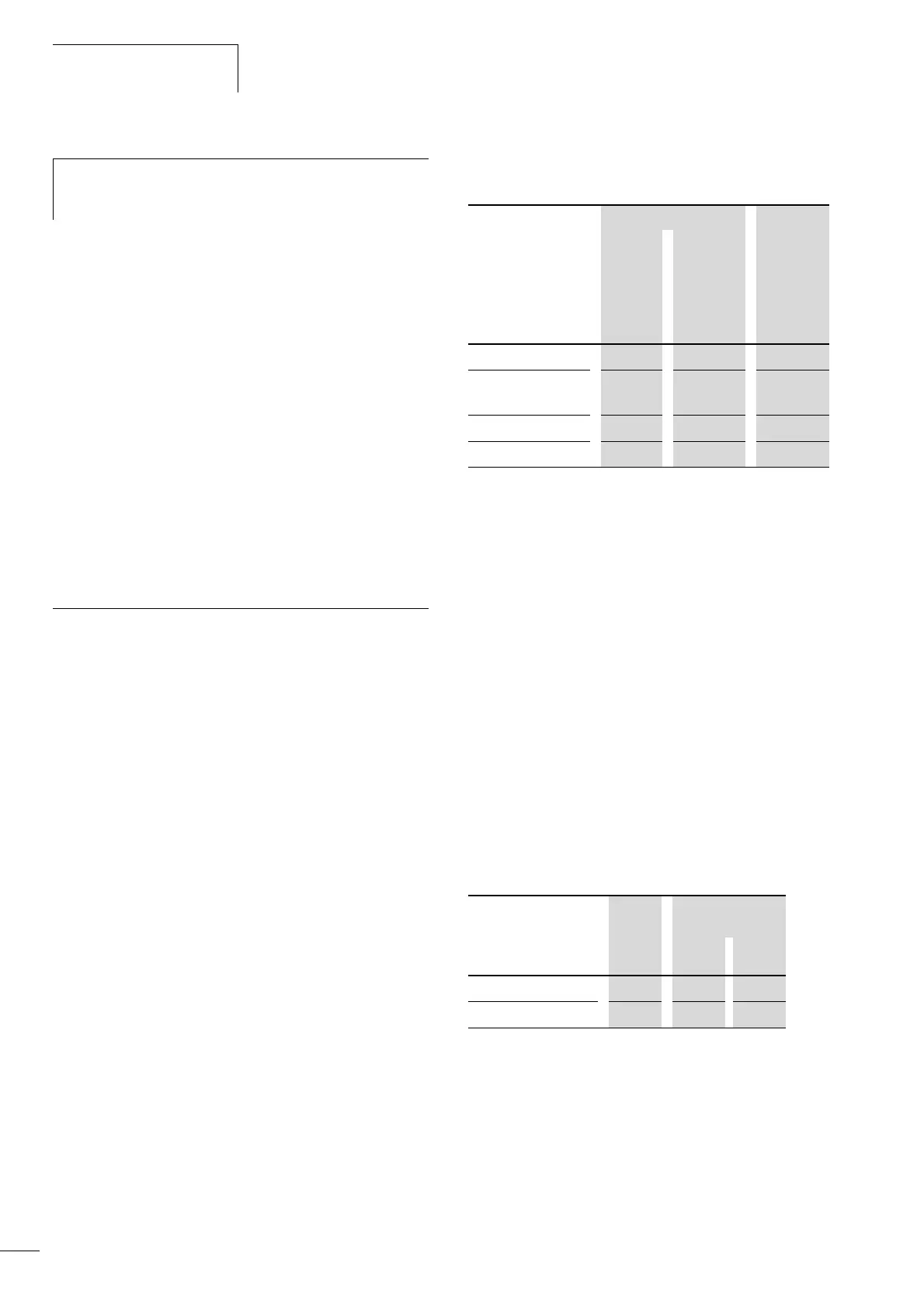
In accordance with the size of the application program, the
following memory values apply:
Function
The task of the CPU is to generate output signals from the
incoming local and central/decentralized signal, in accordance
with the application program.
Input/output signal can be, for instance:
• digital or analog signals
• commands from the text display
1)
• output to the text display
1)
• connections to the programming system
• connections to the CANopen bus interface
• connections to fieldbus modules, if present
• connections to intelligent signal modules, if present.
1) Only with XC-CPU...-XV
Use of the CPU types
h
If an XC100 PLC is replaced by an XC200 PLC, the
interrupt inputs are connected to other physical input
addresses!
XC-CPU101-....(-XV)
C64K-8DI-6DO
C128K-8DI-6DO
C256K-8DI-6DO
Program code 64 Kbyte 128 Kbyte 256 kByte
Program data, of
which:
64 Kbyte 128 Kbyte 256 kByte
markers
4 Kbyte 8 Kbyte 16 Kbyte
Retain data
4 Kbyte 8 Kbyte 16 Kbyte
The XC-CPU...-XV types have an additional 64 kByte flash memory
for text
XC100 Text display
XV-101-...
CPU types K42 K84
XC-CPU101... j – –
XC-CPU101...(-XV)
j j j
 Loading...

