03/05 AWB2724-1453GB
CPU
11
Assembly
LED status indicator
a chapter “Operating states” on page 41.
Operating mode selector switch
The operating modes “Stop” and “Run” are selected by a rocker
switch at the front of the CPU module. Please note that the
position of the operating mode selector switch sets the behaviour
of the CPU. The effectiveness of the software settings depends on
the position of the operating mode selector switch. If the selector
switch is changed to the “Stop” position while the equipment is in
the “Run” mode, then the CPU will switch from the operating
mode “Run” to the “Stop” state at the end of the cycle that is
currently running. The position of the operating mode selector
switch is polled at the end of each cycle, and the controller
switches to the selected state, a chapter “CPU operation”.
Multimedia Card (MMC)/Memory card
The multimedia card is used as an optional backup medium for the
(boot) project and to save recipe data. The operating system
supports memory capacities up to a maximum of 128 MByte. At
present, Moeller offers MMCs in the sizes 16 and 32 MByte, with
the type designations XT-MEM-MM16M and XT-MEM-MM32M.
To write data to the multimedia card, just plug it into the
corresponding MEM CARD slot in the CPU. Use the command
“create boot project” to transfer the project to the MMC.
Erasing functions
Use the browser “Format” command in order to erase the entire
content on the MMC. You can delete the boot project and the
operating system on the MMC using the “Reset (Original)”
command.
Data access to the multimedia card
The “XC100_File” library is contained in the “Lib_CPU101”. It
provides the elements for access to the MMC. It is necessary to add
the respective library to the “Library manager”:
X Change to the library manager and position the mouse pointer
on the field for the libraries. Then press the right-hand mouse
button.
X Select the “Additional library insert” command in the new
opened information window.
X Select the “Lib_CPU101” library and then the “XC100_File”
file. Open this file.
The module is integrated into the library manager with the
“Open” command. The following functions are now available:
• FileClose
• FileDelete
• FileGetSize
• FileOpen
• FileRead
• FileRename
• FileSetPos
• FileWrite.
Further information about these modules can be found in the
“Libraries of the XC100_File.lib” section and the in the manual
“Function Blocks for XSoft” (AWB2786-1456GB).
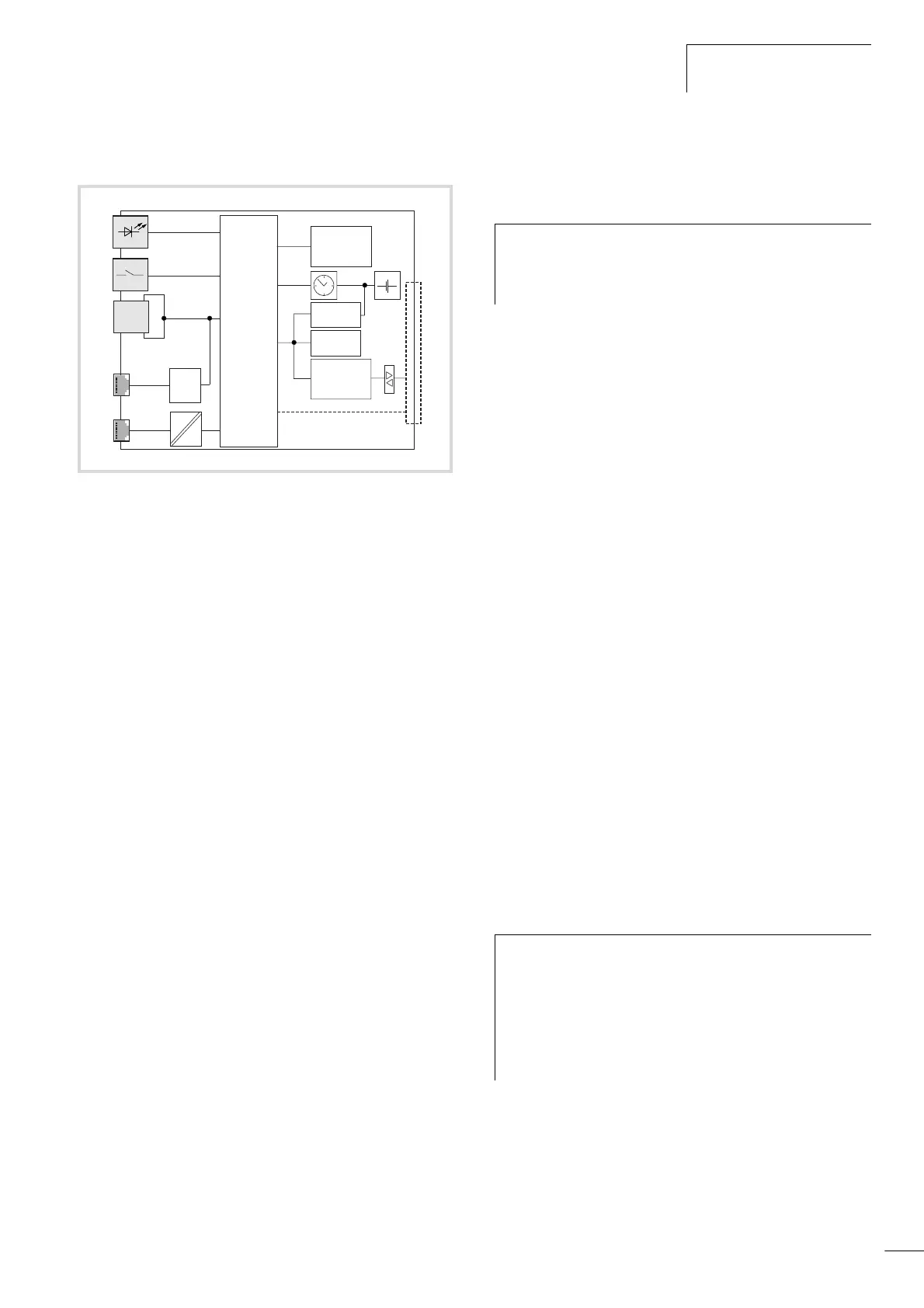
Figure 7: Block diagram of the XC-CPU101
a State indication RUN, Stop, SF
b Operating mode selector switch
c Multimedia card
d Programming device interface:
RS232 on XC-CPU101
e CANopen fieldbus interface
f Voltage monitoring
g I/O bus interface
h XIOC I/O bus (on module rack)
MMC
CAN
RS 232
80C164
FLASH (XV)
+
SRAM
Px
Py
SPI
UART
(LCD/
Touch
Panel)
Adr.
Data
GPIO
a
c
b
e
d
g
f
h
h
From operating system (OS) version 03.03 it is possible to
transfer the operating system to the memory card and to
transfer it from there to other PLCs, a section
“Updating the operating system (OS)” on page 22.
h
Note!
• The “FAT16 file system” is not transaction-safe.
• The control voltage/control may not be switched off
when a File service is still open.
• A voltage failure or shut down of the supply voltage
with an open File service can lead to destruction of the
multimedia card.
 Loading...

